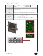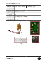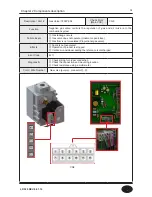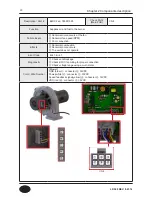
15
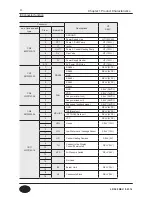
Connector
Descriptions
HT
SELV
no. of location and
type
Pin nr.
Board Silk
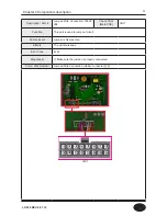
CN9
65001WS-12
1
-
GROUND
-
2
L
Power Supply Line
HT (120VAC)
3
CP1
Pump 1: DHW Pump
HT (120V~)
4
IT
Ignitor
HT (120V~)
5
L(HT)
Pump 2: Central Heating Pump
HT (120V~)
6
GV
Gas Valve
HT (120V~)
7
-
-
-
8
N
Power Supply Neutral
HT (120V~)
9-12
AC Power COM Line
HT (120V~)
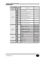
CN1
SMW250-05
1
RS-485
RS485 +
SELV (5VDC)
2
RS485 -
SELV (5VDC)
3
GND
-
4
RS485 +
SELV (5VDC)
5
RS485 -
SELV (5VDC)
CN4
LWD1140-06
1
FAN
Unuse
-
2
GND
SELV (26VDC)
3
VDD
SELV (14VDC)
4
Fan power(start coil)
SELV (26VDC)
5
Fan power(end coil)
SELV (26VDC)
6
Fan speed feedback signal
SELV (14VDC)
CN8
SMW250-04
1
MCU ISP
GND
SELV (5VDC)
2
ISP /Reset port
SELV (5VDC)
3
ISP TOOL0 Data port
SELV (5VDC)
4
VCC
SELV (5VDC)
CN11
LWD1140-16
1
HWL
Unuse
SELV (12V~)
8
2
LWL
Low Water Level Leakage Sensor
SELV (12V~)
10
3
HD
Central Heating Demand
SELV (5V)
11
4
TH
Connect to the Display
Control(Thermostat)
SELV (14V)
12
5
APS
Air Pressure Switch
SELV (14V)
13
6
-
Not Used
-
14
7
BL
Burner Limit
SELV (14V)
15
8
HL
Condensate Block
SELV (14V)
16
■ Connector function
Chapter 1 Product Characteristics
LP-528 REV. 8.01.14
Summary of Contents for EFTC-140F
Page 3: ...1 LP 528 REV 8 01 14 ...
Page 13: ...11 Operation flow chart Chapter 1 Product Characteristics LP 528 REV 8 01 14 ...
Page 14: ...12 Operation flow chart Chapter 1 Product Characteristics LP 528 REV 8 01 14 ...
Page 15: ...13 Wiring Diagram Chapter 1 Product Characteristics LP 528 REV 8 01 14 ...
Page 16: ...14 Wiring Diagram Chapter 1 Product Characteristics Mixing Valve LP 528 REV 8 01 14 ...
Page 42: ...40 Chapter 3 How to use control panel LP 528 REV 8 01 14 ...
Page 67: ...65 Chapter 4 Troubleshooting 1 Flame Detection LP 528 REV 8 01 14 ...
Page 70: ...68 Error code Chapter 4 Troubleshooting LP 528 REV 8 01 14 ...
Page 71: ...69 Chapter 4 Troubleshooting LP 528 REV 8 01 14 ...
Page 72: ...70 Chapter 4 Troubleshooting LP 528 REV 8 01 14 ...
Page 106: ...104 1 Cabinet Replacement Parts Chapter 7 Repair Part Diagram LP 528 REV 8 01 14 ...
Page 107: ...105 Chapter 7 Repair Part Diagram LP 528 REV 8 01 14 ...
Page 108: ...106 2 Combustion System Replacement Parts Chapter 6 Repair Parts Diagram LP 528 REV 8 01 14 ...
Page 109: ...107 Chapter 7 Repair Part Diagram LP 528 REV 8 01 14 ...
Page 110: ...108 Memo LP 528 REV 8 01 14 ...
Page 111: ...109 Memo LP 528 REV 8 01 14 ...
Page 112: ...110 Memo LP 528 REV 8 01 14 ...


