60
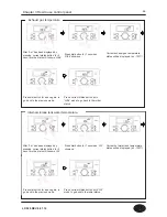
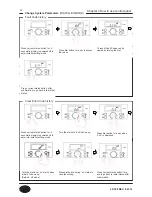
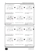
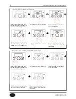
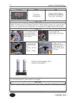
Press ‘current status button’ for 5
secs while display is powered off to
enter into installer setting mode.
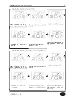
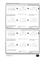
Press ‘current status button’ for 5
secs while display is powered off to
enter into installer setting mode.
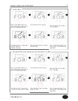
Turn the dial until ‘19:cb’ shows up.
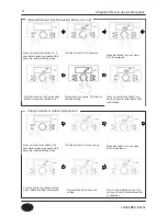
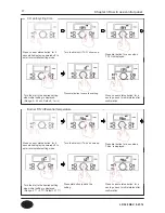
Turn the dial until ‘20:db’ shows up.
Turn the dial to the desired setting
when initial setting is displayed.
(Range: 50~100%, Default : 100%)
Turn the dial to the desired setting
when initial setting is displayed.
(Range: 50~100%, Default : 100%)
Press dial button to save the
setting.
Press dial button to save the
setting.
Press dial button for a sec when
‘19:cb’ is displayed.
Press dial button for a sec when
‘20:db’ is displayed.
CH capacity
DHW heating capacity
Press ‘current status button’ for a
sec to go back to initial status after
confirmation.
Press ‘current status button’ for a
sec to go back to initial status after
confirmation.
Chapter 3 How to use control panel
LP-528 REV. 8.01.14
Summary of Contents for EFTC-140F
Page 3: ...1 LP 528 REV 8 01 14 ...
Page 13: ...11 Operation flow chart Chapter 1 Product Characteristics LP 528 REV 8 01 14 ...
Page 14: ...12 Operation flow chart Chapter 1 Product Characteristics LP 528 REV 8 01 14 ...
Page 15: ...13 Wiring Diagram Chapter 1 Product Characteristics LP 528 REV 8 01 14 ...
Page 16: ...14 Wiring Diagram Chapter 1 Product Characteristics Mixing Valve LP 528 REV 8 01 14 ...
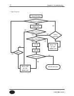
Page 42: ...40 Chapter 3 How to use control panel LP 528 REV 8 01 14 ...
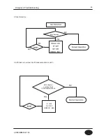
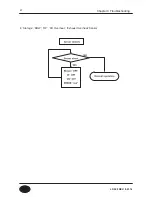
Page 67: ...65 Chapter 4 Troubleshooting 1 Flame Detection LP 528 REV 8 01 14 ...
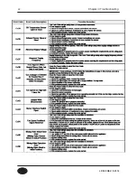
Page 70: ...68 Error code Chapter 4 Troubleshooting LP 528 REV 8 01 14 ...
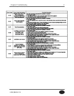
Page 71: ...69 Chapter 4 Troubleshooting LP 528 REV 8 01 14 ...
Page 72: ...70 Chapter 4 Troubleshooting LP 528 REV 8 01 14 ...
Page 106: ...104 1 Cabinet Replacement Parts Chapter 7 Repair Part Diagram LP 528 REV 8 01 14 ...
Page 107: ...105 Chapter 7 Repair Part Diagram LP 528 REV 8 01 14 ...
Page 108: ...106 2 Combustion System Replacement Parts Chapter 6 Repair Parts Diagram LP 528 REV 8 01 14 ...
Page 109: ...107 Chapter 7 Repair Part Diagram LP 528 REV 8 01 14 ...
Page 110: ...108 Memo LP 528 REV 8 01 14 ...
Page 111: ...109 Memo LP 528 REV 8 01 14 ...
Page 112: ...110 Memo LP 528 REV 8 01 14 ...

