16
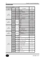
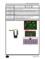
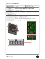
Connector
Description
HT
SELV
no. of location and
type
Pin
nr.
Board
Silk
CN7
LWD1140-14
1
F.S
Flame Detect Sensor
SELV (5VDC)
8
2
OP.S
Operation water temperature sensor
SELV (5VDC)
9
3
DH.S
DHW temperature sensor
SELV (5VDC)
10
4
I.S
Returen water temperature sensor
SELV (5VDC)
11
5
BG.S
Exhaust temperature sensor
SELV (5VDC)
12
6
ST.S
Storage water temperature sensor
SELV (5VDC)
13
7
SP.S
CH Over heat temperature sensor
SELV (5VDC)
14
CN14
SMW250-09
1
IWM
GND
SELV (14VDC)
2
IWM Stepper motor position
SELV (14VDC)
3
VDD
SELV (14VDC)
4
IWM Stepper motor coil X phase
SELV (14VDC)
5
IWM Stepper motor coil Y phase
SELV (14VDC)
6
VDD
SELV (14VDC)
7
IWM Stepper motor coil /X phase
SELV (14VDC)
8
IWM power IWM Stepper motor coil /Y phase
SELV (14VDC)
9
Not Used
-
CN3
SMW250-06
1
WPS
Not Used
SELV (5VDC)
2
Not Used
SELV (5VDC)
3
Not Used
SELV (5VDC)
4
FLUX1
VCC
SELV (5VDC)
5
Water Flow Sensor
SELV (5VDC)
6
GND
SELV (5VDC)
CN5
SMW250-10
1
RPM
FAN RPM Check
SELV (5VDC)
2
GND
SELV (5VDC)
■ Connector function
Chapter 1 Product Characteristics
LP-528 REV. 8.01.14
Summary of Contents for EFTC-140F
Page 3: ...1 LP 528 REV 8 01 14 ...
Page 13: ...11 Operation flow chart Chapter 1 Product Characteristics LP 528 REV 8 01 14 ...
Page 14: ...12 Operation flow chart Chapter 1 Product Characteristics LP 528 REV 8 01 14 ...
Page 15: ...13 Wiring Diagram Chapter 1 Product Characteristics LP 528 REV 8 01 14 ...
Page 16: ...14 Wiring Diagram Chapter 1 Product Characteristics Mixing Valve LP 528 REV 8 01 14 ...
Page 42: ...40 Chapter 3 How to use control panel LP 528 REV 8 01 14 ...
Page 67: ...65 Chapter 4 Troubleshooting 1 Flame Detection LP 528 REV 8 01 14 ...
Page 70: ...68 Error code Chapter 4 Troubleshooting LP 528 REV 8 01 14 ...
Page 71: ...69 Chapter 4 Troubleshooting LP 528 REV 8 01 14 ...
Page 72: ...70 Chapter 4 Troubleshooting LP 528 REV 8 01 14 ...
Page 106: ...104 1 Cabinet Replacement Parts Chapter 7 Repair Part Diagram LP 528 REV 8 01 14 ...
Page 107: ...105 Chapter 7 Repair Part Diagram LP 528 REV 8 01 14 ...
Page 108: ...106 2 Combustion System Replacement Parts Chapter 6 Repair Parts Diagram LP 528 REV 8 01 14 ...
Page 109: ...107 Chapter 7 Repair Part Diagram LP 528 REV 8 01 14 ...
Page 110: ...108 Memo LP 528 REV 8 01 14 ...
Page 111: ...109 Memo LP 528 REV 8 01 14 ...
Page 112: ...110 Memo LP 528 REV 8 01 14 ...


