73
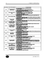
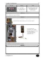
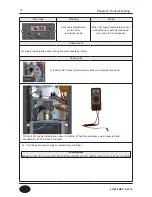
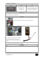
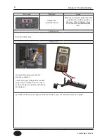
Error code
Meaning
Cause
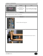
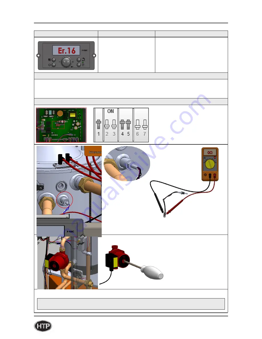
CH overheating
temperature issue
(manual reset)
If temperature on the CH supply
temperature sensor (tagged OP
on connectors) exceeds
203◦F, error Er 16 will appear
Failure event
In case that CH supply temperature is more than 203◦F, water temperature overheating fault occurs and
all output except for fan post-purge is stopped.
Check point
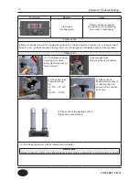
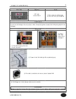
① Check to see if the default
DIP SWITCH settings have been
changed from the factory settings –
assure that default settings are set
to correct overheating condition.
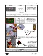
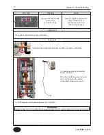
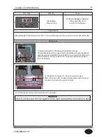
③ Check internal CH pump is
operational. Use a flat head
screw driver to rotate a screw
on the back side of the pump
to ensure the pump internal
shaft is not stuck. Check
pump wiring to ensure proper
connection.
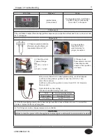
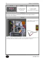
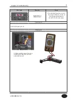
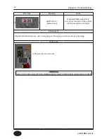
② Please check CH supply temperature sensor (wires are tagged
OP). When the value measured with a multi-meter is 0Ω, replace
the sensor.
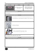
④ If all things are normal, please replace main controller
Chapter 4 Troubleshooting
WARNING
Failure to turn the power off to the appliance before repair could result in serious injury or death.
LP-528 REV. 8.01.14
Summary of Contents for EFTC-140F
Page 3: ...1 LP 528 REV 8 01 14 ...
Page 13: ...11 Operation flow chart Chapter 1 Product Characteristics LP 528 REV 8 01 14 ...
Page 14: ...12 Operation flow chart Chapter 1 Product Characteristics LP 528 REV 8 01 14 ...
Page 15: ...13 Wiring Diagram Chapter 1 Product Characteristics LP 528 REV 8 01 14 ...
Page 16: ...14 Wiring Diagram Chapter 1 Product Characteristics Mixing Valve LP 528 REV 8 01 14 ...
Page 42: ...40 Chapter 3 How to use control panel LP 528 REV 8 01 14 ...
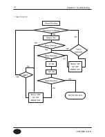
Page 67: ...65 Chapter 4 Troubleshooting 1 Flame Detection LP 528 REV 8 01 14 ...
Page 70: ...68 Error code Chapter 4 Troubleshooting LP 528 REV 8 01 14 ...
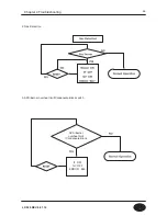
Page 71: ...69 Chapter 4 Troubleshooting LP 528 REV 8 01 14 ...
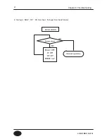
Page 72: ...70 Chapter 4 Troubleshooting LP 528 REV 8 01 14 ...
Page 106: ...104 1 Cabinet Replacement Parts Chapter 7 Repair Part Diagram LP 528 REV 8 01 14 ...
Page 107: ...105 Chapter 7 Repair Part Diagram LP 528 REV 8 01 14 ...
Page 108: ...106 2 Combustion System Replacement Parts Chapter 6 Repair Parts Diagram LP 528 REV 8 01 14 ...
Page 109: ...107 Chapter 7 Repair Part Diagram LP 528 REV 8 01 14 ...
Page 110: ...108 Memo LP 528 REV 8 01 14 ...
Page 111: ...109 Memo LP 528 REV 8 01 14 ...
Page 112: ...110 Memo LP 528 REV 8 01 14 ...

