Component identification 7
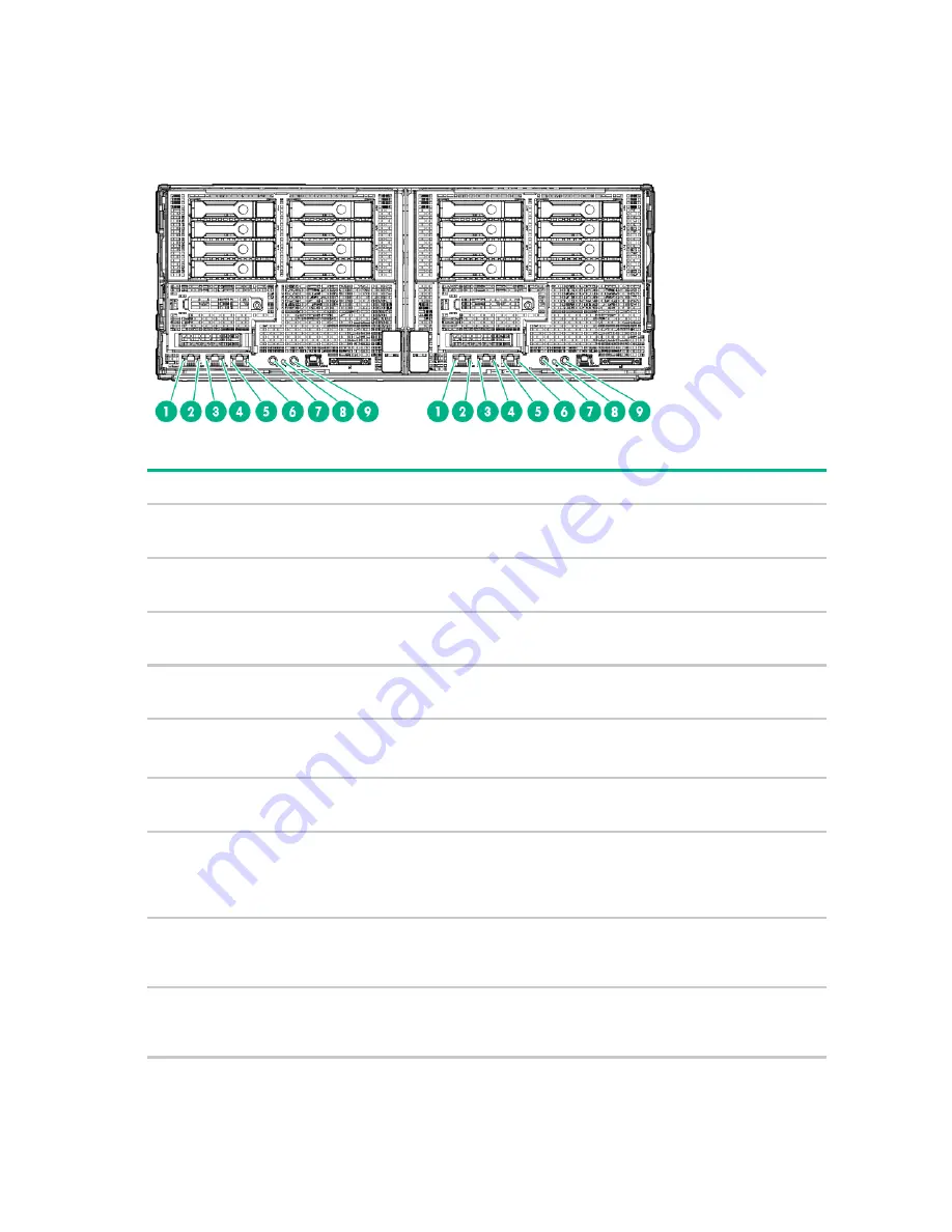
Front panel LEDs and buttons
Item Description
Status
1
iLO 4 speed LED
Green = LAN connection using a GbE link
Amber = LAN connection using a 10 Mbps/100 Mbps link
Off = No link exists
2
iLO 4 status LED
Solid green = Link to network
Flashing green (1 Hz/cycle per sec) = Network active
Off = No network activity
3
NIC 2 status LED
Solid green = Link to network
Flashing green (1 Hz/cycle per sec) = Network active
Off = No network activity
4
NIC 2 speed LED
Green = LAN connection using a GbE link
Amber = LAN connection using a 10 Mbps/100 Mbps link
Off = No link exists
5
NIC 1/iLO 4 status LED
Solid green = Link to network
Flashing green (1 Hz/cycle per sec) = Network active
Off = No network activity
6
NIC 1/iLO 4 speed LED
Green = LAN connection using a GbE link
Amber = LAN connection using a 10 Mbps/100 Mbps link
Off = No link exists
7
Power On/Standby button and
system power LED
Solid green = System on
Flashing green (1 Hz/cycle per sec) = Performing power on
sequence
Solid amber = System in standby
Off = No power present**
8
Health LED
Solid green = Normal
Flashing amber = System degraded
Flashing red (1 Hz/cycle per sec) = System critical
Fast-flashing red (4 Hz/cycles per sec) = Power fault*
9
UID button/LED
Solid blue = Activated
Flashing blue (1 Hz/cycle per sec) = Remote management or
firmware upgrade in progress
Off = Deactivated
* To identify components in a degraded or critical state, see the iLO/BIOS logs and the server troubleshooting guide.
** Facility power is not present, power cord is not attached, no power supplies are installed, power supply failure has
occurred, or the power button cable is disconnected.
Summary of Contents for ProLiant SL270s Gen8
Page 16: ...Operations 16 5 Remove the shipping plates 6 Remove the hard drive cage...
Page 17: ...Operations 17 7 Loosen screws securing the GPU shelf 8 Remove the GPU shelf...
Page 36: ...Hardware options installation 36 5 Remove the shipping plates 6 Remove the hard drive cage...
Page 47: ...Hardware options installation 47 o Left node o Right node...
Page 49: ...Hardware options installation 49 5 Remove the shipping plates 6 Remove the hard drive cage...
Page 50: ...Hardware options installation 50 7 Loosen screws securing the GPU shelf 8 Remove the GPU shelf...
Page 53: ...Hardware options installation 53 4 Remove all shipping brackets 5 Remove the shipping plates...
Page 55: ...Hardware options installation 55 8 Remove the GPU shelf 9 Remove the PCI cage...
Page 59: ...Hardware options installation 59 5 Remove the shipping plates 6 Remove the hard drive cage...
Page 60: ...Hardware options installation 60 7 Loosen screws securing the GPU shelf 8 Remove the GPU shelf...
Page 72: ...Cabling 72 Right node Capacitor pack to FBWC on controller card cabling o Left node...
Page 73: ...Cabling 73 o Right node...
Page 97: ...Support and other resources 97...
Page 98: ...Support and other resources 98...
Page 106: ...Index 106 V ventilation 19 W warnings 21 website Hewlett Packard Enterprise 91...


