


System fan assembly
To remove the system fan assembly:
1.
Disconnect power from the system (
Predisassembly procedures on page 57
), remove the side
access panel (
Side access panel on page 63
), and remove the memory fan (
Memory fan
on page 69
).
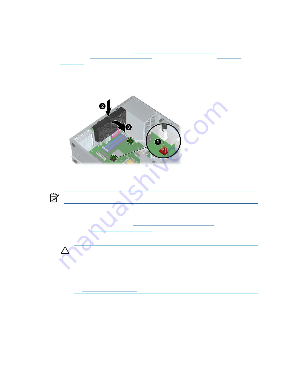
2.
Disconnect the system fan cables from the system board connectors
1
.
3.
Press in on the ribbed release snap of the system fan housing
2
, rotate the fan housing down
3
,
and lift the unit out of the chassis.
Figure 4-16
Removing the system fan
To replace a system fan assembly, there are four plastic tabs that must be aligned carefully in
corresponding chassis holes and then rotate and snap.
NOTE
Be sure to also reinstall the memory fan.
Power supply
1.
Disconnect power from the system (
Predisassembly procedures on page 57
) and remove the side
access panel (
Side access panel on page 63
).
2.
Disconnect the power supply cables from the system board.
CAUTION
Be sure you can differentiate which power cable was disconnected from the
PCI Express x16 graphics card and which power cable was disconnected from the system
board. These two cables have different pin counts and different colors. The PCI Express
power cable has a 6-pin black connector, and the system board power cable has an 8-pin
white connector. When power is present, you must
never
connect the PCI Express power
cable to the system board. If you do so, the system board can be damaged and your warranty
voided. To see a picture of the PCI Express cable and where it must be connected, see
the
PCI installation on page 79
.
3.
Disconnect all other components connected to the power supply, such as optical drives, diskette
drive, hard drives, and select models of add-in cards.
4.
Remove the four screws
1
from the back panel.
5.
Slide the power supply toward the front
2
and lift up
3
to remove it from the chassis.
ENWW
Removal and replacement of components
71
Summary of Contents for Xw6400 - Workstation - 4 GB RAM
Page 1: ...HP xw6400 Workstation Service and Technical Reference Guide User Guide ...
Page 4: ......
Page 15: ...Figure 1 4 Serial number and COA label location ENWW Product features 5 ...
Page 22: ...12 Chapter 1 Product overview ENWW ...
Page 32: ...22 Chapter 2 Installing or restoring the operating system ENWW ...
Page 60: ...50 Chapter 3 System management ENWW ...
Page 69: ...Figure 4 2 System board block diagram ENWW System board components 59 ...
Page 108: ...98 Chapter 4 Removal and replacement procedures ENWW ...
Page 146: ...136 Chapter 5 System diagnostics and troubleshooting ENWW ...
Page 147: ...A Appendix A SAS devices ENWW 137 ...
Page 154: ...144 Appendix A Appendix A SAS devices ENWW ...
Page 160: ...150 Appendix B Appendix B SATA devices ENWW ...
Page 161: ...C Appendix C Connector pins ENWW 151 ...
Page 170: ...160 Appendix C Appendix C Connector pins ENWW ...
Page 173: ...E Appendix E Routine care ENWW 163 ...
Page 180: ...170 Appendix E Appendix E Routine care ENWW ...
Page 186: ...Initial troubleshooting 176 Appendix G Appendix G Quick troubleshooting flowcharts ENWW ...
Page 187: ...No power No power part 1 ENWW No power 177 ...
Page 188: ...No power part 2 178 Appendix G Appendix G Quick troubleshooting flowcharts ENWW ...
Page 189: ...No power part 3 ENWW No power 179 ...
Page 190: ...No video No video part 1 180 Appendix G Appendix G Quick troubleshooting flowcharts ENWW ...
Page 191: ...No video part 2 ENWW No video 181 ...
Page 192: ...No video part 3 182 Appendix G Appendix G Quick troubleshooting flowcharts ENWW ...
Page 193: ...Error messages Error messages part 1 ENWW Error messages 183 ...
Page 194: ...Error messages part 2 184 Appendix G Appendix G Quick troubleshooting flowcharts ENWW ...
Page 195: ...Error messages part 3 ENWW Error messages 185 ...
Page 196: ...No operating system loading 186 Appendix G Appendix G Quick troubleshooting flowcharts ENWW ...
Page 203: ...Non functioning device ENWW Non functioning device 193 ...
Page 204: ...194 Appendix G Appendix G Quick troubleshooting flowcharts ENWW ...


