Hardware options installation 71
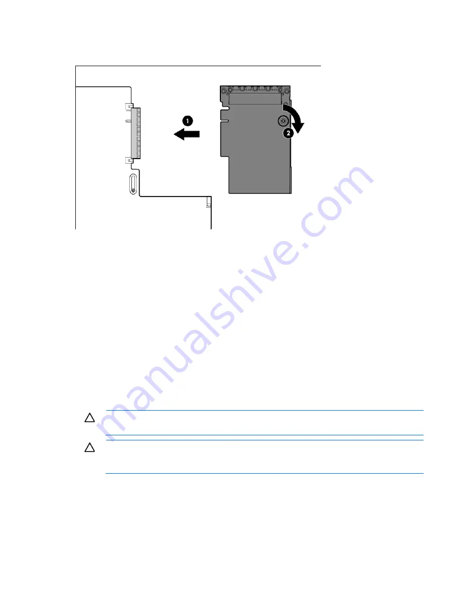
To install the component:
1.
Firmly seat the optional FlexibleLOM in the slot, and then tighten the thumbscrew.
2.
Install the primary PCIe riser cage (on page
31
).
3.
Install the access panel (on page
25
).
4.
Slide the server into the rack.
5.
Connect the LAN segment cables.
6.
Connect each power cord to the server.
7.
Connect each power cord to the power source.
8.
Power up the server (on page
23
).
Expansion board options
The server supports PCI Express expansion boards. The server ships with PCIe riser boards and expansion
slots. PCIe expansion boards are supported with optional riser boards.
Removing the expansion slot blanks
CAUTION:
To prevent damage to the server or expansion boards, power down the server and
remove all AC power cords before removing or installing the PCI riser cage.
CAUTION:
For proper cooling, do not operate the server without the access panel, baffles,
expansion slot covers, or blanks installed. If the server supports hot-plug components, minimize
the amount of time the access panel is open.
To remove the component from either the primary or secondary PCIe riser cage:
1.
Power down the server (on page
23
).
2.
Remove all power:
a.
Disconnect each power cord from the power source.
b.
Disconnect each power cord from the server.
Summary of Contents for ProLiant DL385p Gen8
Page 6: ...Contents 6 Documentation feedback 132 Index 133 ...
Page 65: ...Hardware options installation 65 o 8 or 16 drive SFF o 8 drive LFF ...
Page 91: ...Cabling 91 LFF hard drive cabling Optical drive cabling ...
Page 92: ...Cabling 92 FBWC cabling 8 or 16 drive SFF 8 drive LFF ...
Page 127: ...Support and other resources 127 ...
Page 128: ...Support and other resources 128 ...


