Removal and Replacement Procedures 63
System Fan
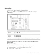
The server has four system fans located on the chassis’ center wall.
The figure below identifies the system fans by their device number and shows their corresponding
cable connections.
Figure 54
System fan connections
Device number
Connector
System fan 1
P8 on the system board
System fan 2
P4 on the system board
System fan 3
P22 on the system board
System fan 4
P21 on the system board
System fans 1 to 3 are for the memory modules and processors, while system fan 4 is for the PCI slots and system
chipsets.
A new system fan can be installed to allow the server to operate properly in case a default system fan
becomes defective.
To remove the system fan:
1.
Disconnect the fan cable from its corresponding board connector.
2.
Release the fan cable from the cable clip securing it to the chassis partition wall.
3.
Squeeze the release tab on the system fan to release it from the chassis.
4.
Lift the system fan away from the chassis.
Summary of Contents for ProLiant DL180 G
Page 12: ...Customer self repair 12 ...
Page 13: ...Customer self repair 13 ...
Page 14: ...Customer self repair 14 ...
Page 15: ...Customer self repair 15 ...
Page 19: ...Illustrated parts catalog 19 ...
Page 82: ...Diagnostic tools and Setup Utilities 82 ...
Page 84: ...Diagnostic tools and Setup Utilities 84 Figure 72 Security menu of the BIOS Setup Utility 2 ...


