155
•
When Router A works normally, Host accesses Router A for portal authentication before accessing
the Internet. When Router A fails, Host accesses the Internet through Router B. The VRRP
uplink/downlink detection mechanism is used to ensure non-stop traffic forwarding.
•
Use the RADIUS server as the authentication/accounting server. In this example, Server takes the
responsibilities of the portal server and the RADIUS server.
•
Router A and Router B use a dedicated physical link as the failover link to transmit stateful failover
related packets.
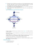
Figure 62
Network diagram for portal stateful failover configuration
Router A
Failover link
Host
9.9.1.2/24
Gateway: 9.9.1.1/24
Router B
GE 0/1
9.9.1.5/24
GE 0/1
9.9.1.6/24
GE 0/2
192.168.0.6/24
GE 0/2
192.168.0.5/24
GE 0/3
Eth1/3
Virtual IP address 2:
192.168.0.1/24
Server
Master
Backup
Virtual IP address 1:
9.9.1.1/24
Master
Backup
L2 Switch
L2 Switch
IP: 192.168.0.111/24
Gateway: 192.168.0.1/24
Configure IP addresses for the host, server, and routers as shown in
and make sure that they
can reach each other.
Make sure that Host can access the authentication server through Router A and Router B before portal
authentication is enabled.
Configure VRRP group 1 and VRRP group 2 to implement backup for downstream and upstream links,
respectively. For more information about VRRP, see
High Availability Configuration Guide
.
For information about stateful failover, see
High Availability Configuration Guide
.
The following describes how to configure the portal server on the iMC. iMC PLAT 5.0(E0101) and iMC
UAM 5.0(E0101) are used in this example.
Configuration procedure
1.
Configure the portal server.
# Configure the portal server.


