5-15.
ALC ADJUSTMENTS (Cont’d)
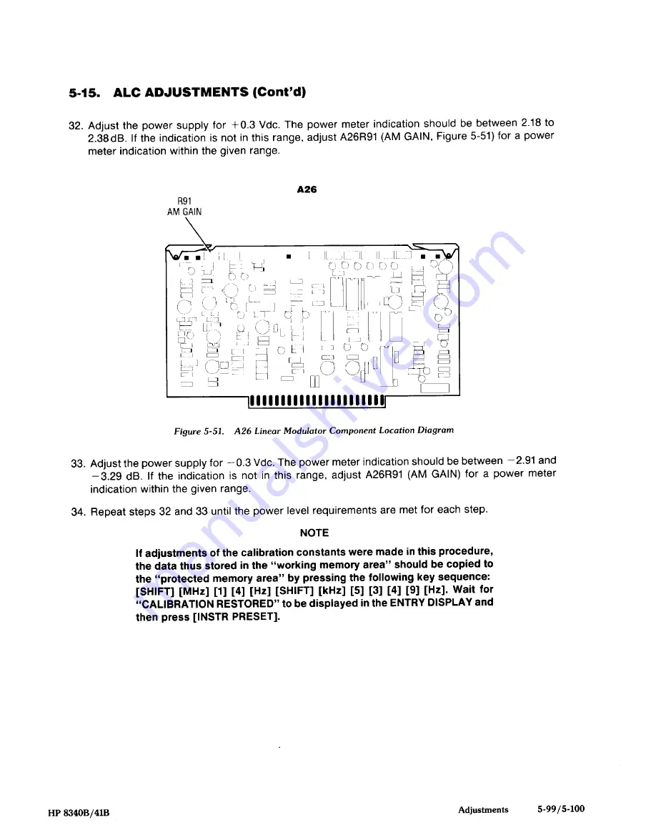
32. Adjust the power supply for +0.3 Vdc. The
power meter indication should be between 2.18 to
2.38dB. If the indication is not in this range, adjust A26R91 (AM GAIN, Figure 5-51) for a power
meter indication
within the given range.
£26
R91
33. Adjust the power supply for —0.3 Vdc. The power meter indication should be between —2.91 and
—3.29 dB. If the indication is not in this range, adjust A26R91
(AM
GAIN) for a power meter
indication within the given range.
34. Repeat steps 32 and 33 until the power level requirements are met for each step.
NOTE
If adlustments of the calibration constants were made in this procedure,
the data thus stored in the “working memory area” should be copied to
the “protected memory area” by pressing the following key sequence:
[SHIFT][MHz] [1] [4] [Hz] [SHIFT][kHz] [5] [3] [4] [9] [Hz]. Wait for
“CALIBRATION RESTORED” to be displayed in the ENTRY DISPLAY and
then press [INSTRPRESET].
Figure 5-51.
A26 Linear Modulator Component Location Diagram
HP 8340B/41B
Adjustments
5-99/5-100


