33
33
E1CG4880210
E1CG4880210
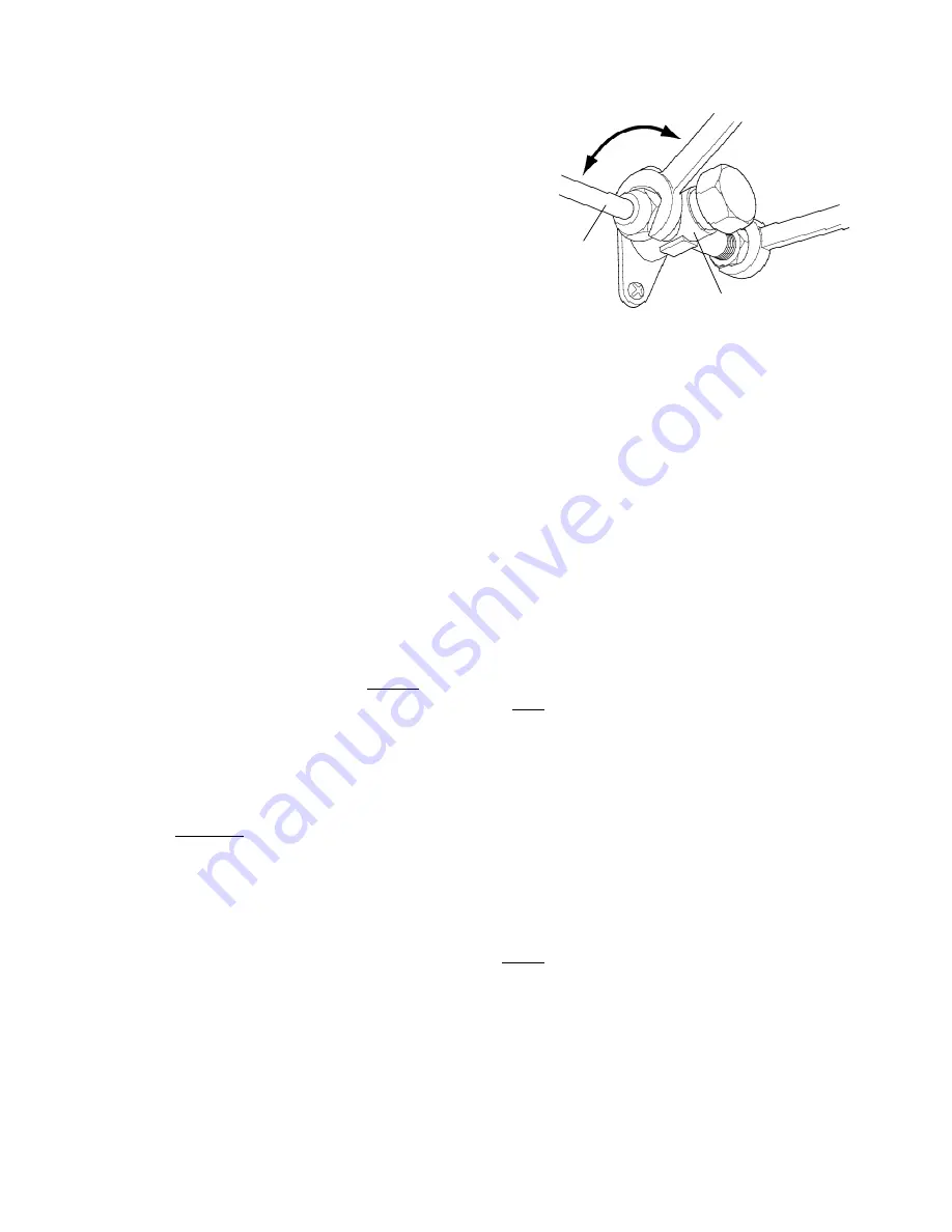
Fig. 19
Fig. 19
Loosen
Loosen
Tighten
Tighten
Copper Tube
Copper Tube
Access Valve
Access Valve
Note:
Note: The tube ends to be flared should be free
The tube ends to be flared should be free
from damage, cracks and burrs and also
from damage, cracks and burrs and also
clear of grease or scraps.
clear of grease or scraps.
4) Connect the flared copper tubes on to the
4) Connect the flared copper tubes on to the
icemaker and Condenser Unit. The two tubes
icemaker and Condenser Unit. The two tubes
have the same diameter so mark them for a
have the same diameter so mark them for a
distinction between the gas line and the liquid
distinction between the gas line and the liquid
line to prevent misconnection. Apply some
line to prevent misconnection. Apply some
clean refrigerant oil of a suitable type to the
clean refrigerant oil of a suitable type to the
surfaces of the Flare before connection and
surfaces of the Flare before connection and
tightening. Support the Access Valve with a
tightening. Support the Access Valve with a
spanner on the flat surfaces when tightening
spanner on the flat surfaces when tightening
the nuts.
the nuts.
Note:
Note:1. Tighten the Flare Nuts to a torque of 38±4 Nm.
1. Tighten the Flare Nuts to a torque of 38±4 Nm.
2. Check the distinction marks on both ends of each copper tubing to make sure the
2. Check the distinction marks on both ends of each copper tubing to make sure the
connections are correct.
connections are correct.
3. The tubes should not vibrate. Fix or secure the tubes to prevent stressing.
3. The tubes should not vibrate. Fix or secure the tubes to prevent stressing.
5) Remove the Service Gauge Port Caps from the Access Valves on the icemaker. Evacuate
5) Remove the Service Gauge Port Caps from the Access Valves on the icemaker. Evacuate
the lines through the Gauge Ports for 20 minutes at max. 0.1 torr. Charge both lines with
the lines through the Gauge Ports for 20 minutes at max. 0.1 torr. Charge both lines with
vapour refrigerant R404A to a pressure of 1 bar. Add nitrogen to raise the pressure to 15
vapour refrigerant R404A to a pressure of 1 bar. Add nitrogen to raise the pressure to 15
bar. Thoroughly leak test the joints with a leak detector or soap bubbles.
bar. Thoroughly leak test the joints with a leak detector or soap bubbles.
6) Evacuate the lines again at max. 0.1 torr. Vapour charge the lines to 1 - 2 bar with refrigerant
6) Evacuate the lines again at max. 0.1 torr. Vapour charge the lines to 1 - 2 bar with refrigerant
R404A. (The actual charge will depend upon the length of tube run.)
R404A. (The actual charge will depend upon the length of tube run.)
Base charge up to 10 m:
Base charge up to 10 m: 2400 g
2400 g
Additional charge for each additional meter:
Additional charge for each additional meter: 40 g
40 g
As the total precharged refrigerant amount in the icemaker and remote condenser is 2400
As the total precharged refrigerant amount in the icemaker and remote condenser is 2400
g, the required refrigerant charge will be:
g, the required refrigerant charge will be:
40 g x [length of tube run - 10] m
40 g x [length of tube run - 10] m
Example
Example - If the length of tubing run is 15 m (i.e. distance between the icemaker and
- If the length of tubing run is 15 m (i.e. distance between the icemaker and
Condenser)
Condenser)
15 m - 10 m = 5 m
15 m - 10 m = 5 m
Base charge = 2400 g (up to 10 m run)
Base charge = 2400 g (up to 10 m run)
Additional charge = 40 g/m
Additional charge = 40 g/m
Required refrigerant charge = 40 g x 5 m =
Required refrigerant charge = 40 g x 5 m = 200 g
200 g
On completion of the refrigerant charge, remove the charging cylinder and charging lines.
On completion of the refrigerant charge, remove the charging cylinder and charging lines.
Refit the Port Caps and tighten to a torque of 10±1 Nm.
Refit the Port Caps and tighten to a torque of 10±1 Nm.
Summary of Contents for IM-240AME
Page 6: ...2 2 E1CG4880210 E1CG4880210 b IM 240DWME Water cooled b IM 240DWME Water cooled ...
Page 7: ...3 3 E1CG4880210 E1CG4880210 c IM 240DSME Remote Air cooled c IM 240DSME Remote Air cooled ...
Page 8: ...4 4 E1CG4880210 E1CG4880210 d IM 240XME Air cooled d IM 240XME Air cooled ...
Page 9: ...5 5 E1CG4880210 E1CG4880210 e IM 240XWME Water cooled e IM 240XWME Water cooled ...
Page 10: ...6 6 E1CG4880210 E1CG4880210 f IM 240XSME Remote Air cooled f IM 240XSME Remote Air cooled ...
Page 11: ...7 7 E1CG4880210 E1CG4880210 g IM 240AME Air cooled g IM 240AME Air cooled ...
Page 62: ...58 58 E1CG4880210 E1CG4880210 b IM 240DWME IM 240XWME b IM 240DWME IM 240XWME ...
Page 63: ...59 59 E1CG4880210 E1CG4880210 c IM 240DSME IM 240XSME c IM 240DSME IM 240XSME ...
Page 64: ...60 60 E1CG4880210 E1CG4880210 d IM 240AME d IM 240AME ...


