Hoshizaki DBF-AS65WE-T Instruction Manual Download Page 26

24

ENGLISH

21) Turn the keg coupler counterclockwise to remove it from the cleaning tank.

22) Thoroughly wash and dry the cleaning sponge and store it for later use.

23) Repeat the above steps 9) to 22) until clear water comes out of the beer tap.

Note:  Receive the water in a mug or glass to check its clearness. Repeat a few 

times until water becomes clear.

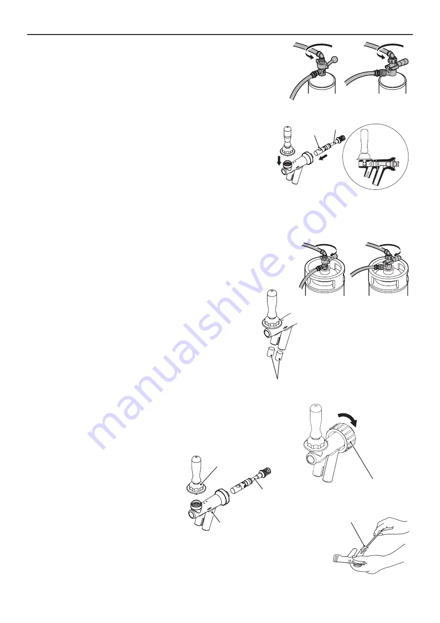
24) Turn the union nut clockwise to remove the beer tap.

25) Loosen the cap nut to disassemble the beer tap. Fit the valve shaft in the 

original (normal) direction while aligning the holes in the beer tap and valve 

shaft (larger hole facing up), and tighten the cap nut.

Note: Assemble the beer tap correctly, or beer cannot be dispensed 

properly.

26) Attach the beer tap on the unit by turning the union nut counterclockwise.

27) Wash the cleaning tank interior thoroughly, turn the tank upside down to dry, and cap it tightly for storage.

28) Hold the bottom of the operation panel unit and pull the front handle toward you to unlock. Pull down the operation panel unit 

until it stops to cover up the beer tap lever.

Note:  To prevent malfunction, do not pull down the operation panel unit with the beer 

tap removed.

29) Turn the keg coupler clockwise to attach it to the beer keg.

Note:  Wash the joint between the keg coupler and beer keg if it is not clean.

30) Wipe off moisture from the end of the beer tap nozzles. Clean and attach 

the nozzle caps (accessory).

Note:  Always attach the accessory nozzle caps at the end of dispensing 

operation or during periods of non-use to prevent entrance of 

insects or dirt into the beer tap nozzles.

6. DISASSEMBLY AND CLEANING OF BEER TAP (WEEKLY)

1) Follow the steps 1) to 7) of “2. BEER CIRCUIT”.

2) Lift up the operation panel unit slowly until it clicks and locks into place.

3) Turn the union nut clockwise to remove the beer tap.

4) Loosen the cap nut to disassemble the beer tap.

5) Use a neutral dishwashing detergent and the accessory brush to clean inside the beer tap and 

valve shaft.

Valve Shaft

Hole

1

2

Rotary Type

Vertical Type

Nozzle Cap

Union Nut

Loosen

Cap Nut

Valve Shaft

Nozzle

Rotary Type

Vertical Type

Brush

Summary of Contents for DBF-AS65WE-T

Page 1: ...DBF AS65WE T L1B078101 103119 AUTOMATIC DRAFT BEER DISPENSER INSTRUCTION MANUAL 3 16 Minamiyakata Sakae cho Toyoake Aichi 470 1194 Japan...

Page 2: ...15 5 SETTING LIQUID AND FOAM AMOUNTS 16 a LARGER MUG SETTING 16 b SMALLER MUG SETTING 16 6 DISPENSING 17 a AUTOMATIC DISPENSING 17 b STOPPING AUTOMATIC DISPENSING 17 c MANUAL DISPENSING 17 d SWITCHIN...

Page 3: ...ous The manufacturer will not be held liable or responsible for any damage caused by improper incorrect and unreasonable use The installation and relocation if necessary must be carried out by qualifi...

Page 4: ...ode Stop Button Press once Manually stops the beer tap or platform operation Press and hold Resets the display indication e g number of mugs Foam Button In ready mode Press and hold to dispense foam I...

Page 5: ...er Hose Adapter 2 O Ring S P10A 2 Spanner 1 Hook 1 Hook Mounting Screw 2 Cylinder Chain 1 O Ring L P21 1 Grille 1 Platform 2 3 UNPACKING WARNING Children should not be allowed in reach of the packagin...

Page 6: ...level foundation for the dispenser NOTICE Do not place anything to obstruct the ventilation louvers IMPORTANT Normal operating ambient temperature should be within 5 C to 32 C cooling water temperatu...

Page 7: ...g Distance A 274 mm Distance B 388 mm After Adjustment Distance a 244 mm Distance b 328 mm b DRAIN PAN To attach the drain pan accessory and grille accessory 1 lift up the front of the drain pan 2 pus...

Page 8: ...d 12th levels The top of the mug must fit the mark on the back plate when positioned on the platform See the table on the next page for the mug heights and platform positions 3 After adjusting the pla...

Page 9: ...175 Upper 190 Upper 180 7 Lower 195 Lower 185 Upper 200 Upper 190 8 Not available Lower 195 Upper 200 9 Lower 205 Upper 210 10 Lower 215 Upper 220 11 Lower 225 Upper 230 12 Lower 235 Upper 240 Note 1...

Page 10: ...an undamaged gasket to prevent the risk of gas leaks If not contact the liquor shop beer company or distributor to install a new gasket Stand the CO2 gas cylinder upright and fix it securely with the...

Page 11: ...connect the CO2 gas hose push it all the way in 2 To disconnect the CO2 gas hose push and hold part 1 with fingers and pull out the hose 2 Beer Hose 1 Attach the O ring S P10A accessory to the smaller...

Page 12: ...ottom 8 Pull the beer tap lever toward you to pour water out of the liquid nozzle 9 Check the CO2 gas circuit for gas leaks If it is leaking correct the hose connections 10 Check the beer circuit for...

Page 13: ...formed for more than 1 minute the dispensing mode is resumed In that case go back to step 2 above 10 USER SETTINGS To make or change settings Press and hold the set button for 3 seconds to enter the s...

Page 14: ...ense button 0 0 1 U09 Mug tilting operation 0 Yes mug is tilted while beer is being dispensed 1 No mug is kept upright while beer is being dispensed 0 0 1 U10 Reset number of mugs 0 Manual 1 Manual or...

Page 15: ...water tank up with approx 27 L of distilled water to the water level line marked inside the water tank 4 Use a conductivity meter if measuring the electric conductivity 5 Close the top cover 3 CHECKS...

Page 16: ...of CO2 gas from beer The higher the beer keg temperature is the easier the CO2 gas separates and a higher gas pressure is required Beer Keg Temperature Gas Pressure Note The values are for reference o...

Page 17: ...ontact your dealer supplier To prevent electric shock or fire do not turn it back on In case of trouble unplug the unit or disconnect the main power supply and immediately contact your dealer supplier...

Page 18: ...y vary depending on the performance of the regulator controlling the CO2 gas pressure If the set amounts vary too much the regulator must be replaced Empty the drain pan frequently before it overflows...

Page 19: ...tact your dealer supplier To stop the automatic dispensing operation halfway through 1 Press the stop button The platform stops at that position When the stop button is pressed again the platform goes...

Page 20: ...is factory set to 0 Setting A mainly beer In the manual dispensing mode the unit will not stop dispensing even if the sold out lamp lights up Be careful with the keg level while dispensing beer When...

Page 21: ...After draining the water tank remove the top cover to dry the water tank interior III MAINTENANCE WARNING Before carrying out any cleaning or maintenance operations unplug the dispenser from the elect...

Page 22: ...Vertical type Unlock and lift the keg coupler handle all the way up 3 Turn the regulator adjust dial to set the pressure to 0 MPa 4 Close the main valve of the CO2 gas cylinder by turning it clockwise...

Page 23: ...op button to close the beer tap 18 Close the beer circuit Rotary type Turn the keg coupler handle counterclockwise until it stops Vertical type Unlock and lift the keg coupler handle all the way up 19...

Page 24: ...KLY To flush the beer circuit use the cleaning tank specified by the beer company Follow the instructions provided with the cleaning tank 1 Follow the steps of 2 BEER CIRCUIT 2 Lift up the operation p...

Page 25: ...to set the pressure to 0 15 MPa 15 Open the beer circuit Rotary type Turn the keg coupler handle clockwise until it stops Vertical type Push down the keg coupler handle until it locks in place Note I...

Page 26: ...nt handle toward you to unlock Pull down the operation panel unit until it stops to cover up the beer tap lever Note To prevent malfunction do not pull down the operation panel unit with the beer tap...

Page 27: ...8 EXTERIOR WEEKLY The exterior is easily contaminated Always keep it clean NOTICE To prevent damage do not use any cleaner other than a neutral cleaner on the plastic exterior 1 Wipe with a cloth con...

Page 28: ...e gas and beer hoses for damage deformation and water leak marks stains If any problem is found contact your dealer supplier 3 ATTACHMENT PLUG AND POWER CORD ANNUALLY BIANNUALLY WARNING Check periodic...

Page 29: ...blown out Contact your dealer supplier Power failure Wait until power is resumed Beer is not cold No ice in the water tank Wait until ice is produced Less than 8 to 13 hours after the power switch ea...

Page 30: ...at the time of setting Too little or too much liquid or foam The regulator adjust dial has been turned after liquid amount adjustment Readjust the CO2 gas pressure and the liquid and foam amounts Sol...

Page 31: ...A Electric Consumption Motor 285 345W Ice Making Time 10 hrs ambient temp 30 C initial cooling water temp 25 C Dispensing Capacity 65 L 30 C to 8 C 4 hrs Dimensions 367mm W x 674mm D x 764mm H Refrige...

Reviews: