background image

6 Other Functions

40

6.2.4

Alarm history check

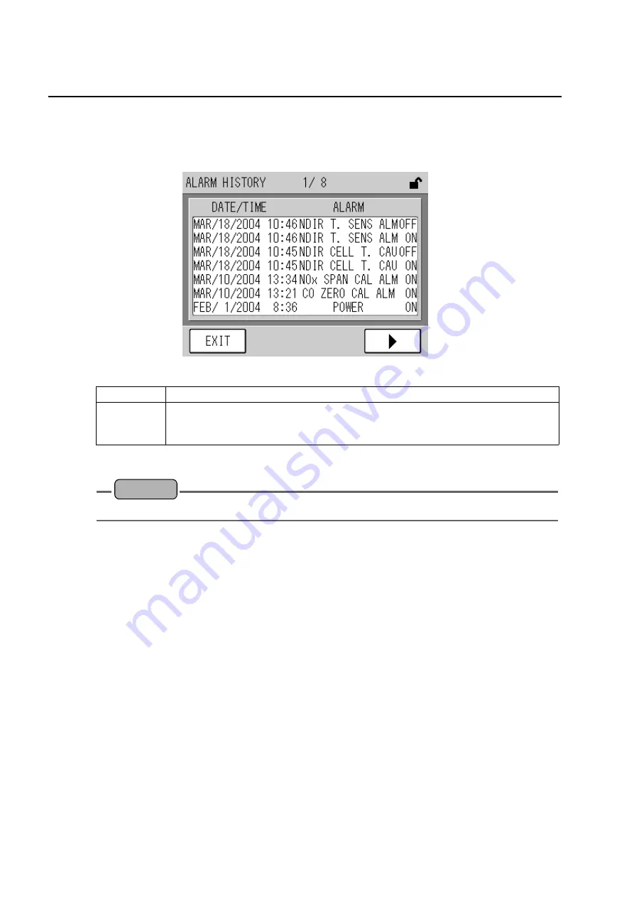
Pressing the [ALARM HISTORY] button in the MENU 2/5 (MANTENANCE/DATA menu)
screen will display the ALARM HISTORY screen. In this screen, the alarm history can be
confirmed.

Fig. 35  ALARM HISTORY screen

Maximum 56 alarm histories can be memorized, and are displayed on the screen from the
latest record. Press the [

W

] key and [

X

] key to switch the screen.

Reference

For detailed information of each alarm, refer to " 8.1 Alarm Type and Countermeasure " (page 75).

ON

Indicates that the alarms or cautions have occurred.

OFF

Indicates that the alarms have been released.
For the alarms of “POWER,” “CALIBRATION ALARM,” and “CALIBRATION
CAUT.”, the indication of “OFF” is not recorded even when they are released.

Summary of Contents for ENDA-5000

Page 1: ...Stack Gas Analysis System ENDA 5000 Instruction Manual CODE GZ9100497217D...

Page 2: ...e following cases none of the warranties set forth herein shall be extended z Any malfunction or damage attributable to improper operation z Any malfunction attributable to repair or modification by a...

Page 3: ...ided could result in death or serious injury CAUTION This indicates a potentially hazardous situation which if not avoided may result in minor or moderate injury It may also be used to alert against u...

Page 4: ...Labels and Location Label location Electric shock label 1 Electric shock label 2 Hot component label Front inside Side...

Page 5: ...E COVER WHILE POWERED ON COULD RESULT IN ELECTRIC SHOCK BE SURE TO TURN OFF POWER PRIOR TO OPENING THE COVER WARNING ELECTRICAL GROUND INSTRUMENT TO AVOID ELECTRICAL SHOCK C A U T I O N HOT COMPONENT...

Page 6: ...ot connect the power cable and discharge the internal circuits before operations Use protective equipment Wear protective glasses gloves etc if necessary Cautionary items against noise The product is...

Page 7: ...Long time Storage 12 4 Measurement Screen Basic Panel 13 5 Calibration 17 5 1 Calibration Screen CAL screen 17 5 2 Preparation of Calibration 19 5 2 1 Gas connection check 19 5 2 2 Setting calibratio...

Page 8: ...primary filter element 61 7 3 2 Replacing the secondary element 62 7 3 3 Replacing the scrubber 63 7 3 4 Replacing the mist catcher 64 7 3 5 Replacing the pump diaphragm 65 7 3 6 Cleaning the cabinet...

Page 9: ...ns 92 10 1 Purge Functions 92 10 1 1 Principle of operation 92 10 1 2 Purge setting 93 10 1 3 Purge start 99 10 2 O2 Correction 100 10 2 1 O2 conversion correction setting 100 10 3 Rolling Average Int...

Page 10: ...6 MENU 1 5 OPERATION menu screen 32 Fig 27 MEAS RANGE screen 33 Fig 28 NOx RANGE screen 33 Fig 29 MENU 2 5 MAINTENANCE DATA menu screen 35 Fig 30 ANALOG INPUT 1 screen 36 Fig 31 ANALOG INPUT 2 screen...

Page 11: ...URGE DELAY TIME screen 98 Fig 74 MENU 1 5 OPERATION menu screen 99 Fig 75 MENU 4 5 OPTION menu screen 100 Fig 76 O2 CORRECTION SET screen 101 Fig 77 O2 CORRECTION MODE screen 102 Fig 78 O2 SET VALUE 1...

Page 12: ......

Page 13: ...p to 5 components For the analyzers of NOx SO2 CO and CO2 non dispersive Infrared ray absorptiometry with cross modulation system NDIR is applied to enable excellent stability and accuracy For O2 anal...

Page 14: ...r Performs the gas processing Drain separation Sulfuric mist processing NO2 to NO conversion Dust removal processing Cooling 5 Panel switch Refer to 2 2 Panel Switch in Cabinet page 3 6 Cylinder conta...

Page 15: ...f the primary filter heater Serves also as a power switch of primary filter heater 5 Heated tube CP heated tube switch A protection device circuit protector of the heated tube Maximum length of the he...

Page 16: ...output Approx 100 VA Purge specification Approx 200 VA Noise filter Arrestor Heated tube CP 15 A Primary filter CP 3 A Main power ELB 30 A Meter CP 7 5 A Analyzer SW Panel heater CP 5 A Sampling pump...

Page 17: ...aration The removed drain is captured and collected into the drain trap 2 Electric cooler Pre cooler Cools down the gas that has reached to the dew point in the cabinet by drain separator The electric...

Page 18: ...ry to control NDIR flow 18 Capillary 2 A capillary to control MPA sample flow 19 Capillary 3 A capillary to control MPA carrier gas flow 20 Analyzer 2 MPA is incorporated No Name Description 21 Air fi...

Page 19: ...2 Name of Each Part 7 Fig 5 Parts layout 1 12 3 2 10 24 31 15 16 17 18 19 20 Contained in the analyzer case 9 29 11 30 14 27 23 6 22 Zero gas generator 25 21 5 8 26 28 4 22 Scrubber 13 7...

Page 20: ...er starts being discharged from the drain trap 2 lower drain trap Fig 6 Drain trap watering Q Connecting calibration gas cylinder and tubes Connect the standard gas cylinder pressure regulator to the...

Page 21: ...ng is indicated in the analyzer When any alarms are indicated confirm the situation and take a suitable action referring to 8 1 Alarm Type and Countermeasure page 75 Note The operation lamp lights up...

Page 22: ...rge for 5 minutes or longer 2 Turn OFF the pump 1 switch and 2 switch 3 Turn OFF the analyzer switch 4 Turn OFF the primary filter CP heated tube CP and panel heater CP 5 Turn OFF the main power ELB 6...

Page 23: ...r purge continue to start 3 3 2 Power interruption 1 When AIC or purge optional are in progress at the power interruption AIC or purge start from the beginning of each sequence When the automatic cali...

Page 24: ...ding on the sample condition If your hand or skin contacts the water in the drain trap flush away with water completely 3 When the calibration gas is connected ensure the main valve is closed Note To...

Page 25: ...to page 8 System setting LCD adjustment Refer to page 46 Current time setting Refer to page 48 Password setting Refer to page 49 Calibration preparation Setting of calibration range and span gas conce...

Page 26: ...r press the screen too strong The screen may be malfunctioned Fig 7 MEAS screen 1 Measurement value display Pressing the COR key optional switches the MEAS screen to the COR screen Fig 8 MEAS screen 2...

Page 27: ...LOCK button is available This function allows preventing irresponsible setting change due to misoperation Measurement component display The measurement component currently set is displayed Measurement...

Page 28: ...the LCD backlight lights up again When the In maintenance switch is ON however the backlight remains lit Measurement range The current measurement range is displayed When the measurement value exceed...

Page 29: ...to perform automatic calibration Reference Refer to 5 3 AIC page 22 Manual calibration A calibration method given by manual operation with flowing the calibration gas voluntarily Reference Refer to 5...

Page 30: ...ng function as follows ALARM The calibration coefficient is out of the normal range The calibration coefficient is not revised but the previous calibration coefficient is used for the concentration op...

Page 31: ...ew cylinder if the pressure is within approximately 1 MPa 5 2 2 Setting calibration range and span gas concentration Set the range for calibration and span gas concentration 1 Press the MENU key in th...

Page 32: ...n Tip To cancel the changes press the CANCEL key The changes are canceled and the screen returns to the CALIBRATION SET screen 6 Press the EXIT key in the CALIBRATION SET screen The screen returns to...

Page 33: ...BRATION SET screen 4 Press the EXIT key twice The screen returns to the MEAS screen Tip The span concentration value can be set for the calibration range of each measuring component Note If changing t...

Page 34: ...ut Adjust the calibration gas flow by referring to Q Calibration gas flow control page 30 5 3 1 AIC setting Set the AIC conditions in the AIC screen The AIC conditions are z Mode z Start time z Interv...

Page 35: ...3 5 SETTING menu screen Note If changing the AIC setting during AIC AIC appears on the screen and rejects the operation Setting item Description Mode Sets the starting procedure of AIC Pressing the ri...

Page 36: ...ed and the screen returns to the AIC SET screen Note AIC based on the internal clock and AIC from external contact input cannot be set at the same time Setting item Description DISABLE The AIC start i...

Page 37: ...possible date When this happens the existing date closest to that before the set date is automatically selected z When the start time previous to the current time is set the setting value of start tim...

Page 38: ...ch setting is to be changed will reverse the value display Change the value by the T and S button and press the SET key 3 Change the setting and the screen returns to the AIC SET screen Note The avail...

Page 39: ...een 2 Press the AIC key AIC starts Note Pressing the AIC key during the AIC can stop the AIC Q Start from external contact input 1 Select EXTERNAL in the AIC MODE screen page 24 Fig 18 2 The automatic...

Page 40: ...ss the button of item to be set and press the SET key The setting is changed and the screen returns to the CAL screen Calibration mode Setting item Description ZERO GAS Select ZERO to perform zero cal...

Page 41: ...he screen the RELEASE key also appears on the screen For CAUT The calibration result is revised but for ALARM the result is not revised To release ALARM or CAUT press the RELEASE key To finish the cal...

Page 42: ...ure regulator needle to adjust the flowmeter indication on the analyzer front panel is 0 6 L min 0 1 L min Note When the air is used as zero gas it is span gas for the O2 analyzer flow control of zero...

Page 43: ...MENU 3 5 SETTING page 42 Fig 37 z MENU 4 5 OPTION page 43 Fig 38 z MENU 5 5 SYSTEM page 45 Fig 39 Soon after the MENU screen appears the OPERATION menu screen is displayed Pressing each key allows th...

Page 44: ...tting and press the SET key Change the setting in each setting screen and press the EXIT key The screen returns to the MENU 1 5 OPERATION menu screen 4 Press the EXIT key in the MENU 1 5 OPERATION men...

Page 45: ...of the component to be set Fig 28 NOx RANGE screen Press the button of the component to be set as a measurement component and execute the setting Setting item Description RANGE 1 Selects RANGE 1 RANGE...

Page 46: ...automatically switches in the following conditions RANGE 1 to RANGE 2 At more than 90 of the concentration of RANGE 1 RANGE 2 to RANGE 1 At less than 80 of the concentration of RANGE 1 The concentrati...

Page 47: ...DATA menu screen Tip To cancel the change press the CANCEL key The change is canceled and the screen returns to the MENU 2 5 MAINTENANCE DATA menu screen 4 Press the EXIT key in the MENU 2 5 MAINTENAN...

Page 48: ...button in the MENU 2 5 MAINTENANCE DATA menu screen will display the ANALOG INPUT screen In this screen the analog input value can be confirmed The screen depends on each specification Fig 30 ANALOG I...

Page 49: ...tage for CO analyzer measurement CO Comp Displays the analog signal and voltage of the detector for CO analyzer compensation SO2 Main Displays the analog signal and voltage of the detector for SO2 ana...

Page 50: ...ig 32 ANALOG OUTPUT screen Press the setting part of the channel to be output Pressing the set value switches the value in order 0 10 20 to 100 MEAS 0 After setting press the OUTPUT key The set condit...

Page 51: ...een Maximum 15 records of calibration coefficient history can be memorized for each component Pressing the X key will display the next screen Press the the W key and X key to switch the screen Pressin...

Page 52: ...stories can be memorized and are displayed on the screen from the latest record Press the W key and X key to switch the screen Reference For detailed information of each alarm refer to 8 1 Alarm Type...

Page 53: ...l display the CO PEAK COUNT screen In this screen the number of CO peak count times can be confirmed Fig 36 CO PEAK COUNT screen Reference For the peak count setting refer to 10 5 1 Peak count set pag...

Page 54: ...TING screen appears Pressing each button allows the corresponding operations as follows 3 Change the setting in each setting screen and press the EXIT key The setting is changed and the screen returns...

Page 55: ...n page 100 ROLLING AVERAGE TIME SET Displays the ROLLING AVERAGE TIME SET screen This is the optional function and not displayed in the standard specifi cation For the operation procedure refer to 10...

Page 56: ...he setting in each setting screen and press the EXIT key The setting is changed and the screen returns to the MENU 4 5 OPTION menu screen 4 Press the EXIT key in the MENU 4 5 OPTION menu screen The sc...

Page 57: ...e EXIT key The setting is changed and the screen returns to the MENU 5 5 SYSTEM menu screen 5 Press the EXIT key in the MENU 5 5 SYSTEM menu screen The screen returns to the MEAS screen LCD ADJUST Dis...

Page 58: ...t touch panel operation to the automatic light OFF of the LCD backlight At shipment it is set to 30 minutes Fig 40 LCD ADJUST screen The current BACK LIGHT TIME PERIOD setting is indicated in button c...

Page 59: ...to ON Even with time setting the backlight will be always lit when the In maintenance switch is ON 3 Press the SET key The BACK LIGHT PERIOD time is changed and the screen returns to the LCD ADJUST s...

Page 60: ...ange the time but applies the time before change z The setting per second is not possible pressing the SET key automatically sets to 00 second z It is not available to change into an impossible date W...

Page 61: ...cording to the message on the screen input the password currently set The screen to input a new password will appear Note The password at shipment is set to 0000 Pressing each key allows the correspon...

Page 62: ...gain and press the SET key The input password is checked with the new password When both of them accord each other the password is changed into a new one and the screen returns to the MENU 5 5 SYSTEM...

Page 63: ...CH PANEL ADJUST button in the MENU 5 5 SYSTEM menu screen will display the TOUCH PANEL ADJUSTMENT screen 2 Touch the part on the upper left of screen and search the position where turns to Fig 46 TOUC...

Page 64: ...nfirmation is possible In trying to change the setting the message In Key Lock appears Note To use the key lock function the password is required Set the password beforehand according to the 6 5 3 Pas...

Page 65: ...n Input the password currently set Pressing each key allows the corresponding operation as follows Note The password at shipment is set to 0000 KEY LOCK Enables KEY LOCK ON KEY UNLOCK Disables KEY LOC...

Page 66: ...k the alarms currently occur Note For checking the alarm history refer to 6 2 4 Alarm history check page 40 1 Go to the MEAS screen Fig 51 MEAS screen 2 Press the ALARM key The ALARM screen appears Fi...

Page 67: ...nder high pressure Handle it carefully Check the installation state of the pressure regulator Check the temperature of installation site Storage and operating temperature is specified as 40 C or less...

Page 68: ...ge 61 Holder cap 3 months Replace O ring 6 months Replace after applying Dyflon grease Heated tube piping 3 months If clogging is found clean it by instrumental air Be sure to clean it with the inlet...

Page 69: ...en when the main power ELB is not charged At inspection do not touch the terminal part Check item Contents of inspection Reference Calibration Perform the calibration and confirm that the zero and spa...

Page 70: ...nce is below 5 M at 500 V megger CAUTION Checking Arrestor In checking the arrestor the breaker at the user side or the leak breaker that supplies power to the analyzer needs to be OFF This is a hazar...

Page 71: ...t Silica gel cap Regulator Regulator O ring Regulator spectacle O ring Flowmeter Analyzer casing Power ZWS75AF 5 J With Electrolytic condenser Power ZWS150AF 24 J Solid relay G3R ODX02SN Replace when...

Page 72: ...cell Detector CO2 Detector NO Detector SO2 Detector CO Printed board AP PRE 10 Solenoid valve Replace Capillary SA 152 QJ Replace when broken O2 analyzer Detector O2 Printed board EN PRE 02 Cell O2 E...

Page 73: ...set to the holder Apply the Dyflon grease standard accessory to the element cap holder cap and the O ring 4 Attach the holder to the original position Fig 53 Replacing the primary filter element CAUTI...

Page 74: ...y on the O ring 5 Replace the filter element and assemble it by the reversed procedure Note z For element use PA 5L filter when the SO2 analyzer is included or use GC 90 filter when the SO2 analyzer i...

Page 75: ...e connected joint 3 Pull up the scrubber a little and pull off to the front 4 Replace the scrubber and assemble it by the reversed procedure Note Attach the scrubber with the correct orientation so th...

Page 76: ...d joint 3 Pull up the mist catcher a little and pull it off to the front 4 Replace the mist catcher and assemble it by the reversed procedure Note Attach the mist catcher with the correct orientation...

Page 77: ...nce gauge between the oscillation piece and transformer and adjust the diaphragm position so that the clearance gauge can pass through After the adjustment tighten the screw 3 9 Attach the cover and a...

Page 78: ...a stop frame 2 Clean the filter and assemble it by the reversed procedure When the filter is deteriorated replace it Fig 58 Cabinet ventilation filter Note For the heater inside the panel attach the c...

Page 79: ...replace it 6 Replace the catalyst tube and assemble it by the reversed procedure 7 Connect the power connector and warm it up for approximately 30 minutes Note Attach the catalyst tube with the corre...

Page 80: ...it 6 Replace the catalyst tube and assemble it by the reversed procedure 7 Connect the power connector and warm it up for approximately 30 minutes Note Attach the catalyst tube with the correct orient...

Page 81: ...p 2 switches 2 Disconnect the tube connected to the cap 3 Remove the cap and take out the air filter 4 Perform cleaning inside the pot 5 Replace the air filter and assemble it by the reversed procedur...

Page 82: ...to the protective filter 5 Take out the silica gel with the protective filter 6 Remove the cap and the protective filter from silica gel 7 Replace the protective filter 8 Replace the silica gel and a...

Page 83: ...pump 1 and pump 2 switches 3 Disconnect the connected joint 4 Pull up the halogen scrubber a little and pull off to the front 5 Replace the halogen scrubber and assemble it by the reversed procedure N...

Page 84: ...n the pressure regulator is discharged when removing the cylinder provide adequate ventilation When using poisonous gas use protective gear such as a gas mask 5 Replace the old cylinder with a new cyl...

Page 85: ...is applied 3 Record the numerical value of the primary pressure at this time 4 Close the valve of the gas cylinder 5 Record the numerical value of the primary pressure after 10 to 15 minutes and chec...

Page 86: ...he specified flow Use the needle of the pressure regulator with a needle valve or the secondary pressure regulating handle of the secondary pressure variable pressure regulator Reference For introduci...

Page 87: ...ndicates that the temperature compensation sensor for NDIR detector is being abnormal Contact HORIBA Analyzer caution MPA Temperature Sensor Alarm Indicates that the temperature compensation sensor fo...

Page 88: ...tside Confirm that the temperature at installation part is within the range of 5 C to 50 C If the specification is with the panel heater confirm that the panel heater CP is ON When the temperature is...

Page 89: ...panel confirm that there is the specified flow If the wrong gas type is selected perform the calibration again with the correct gas type If the residual pressure of calibration gas is within 1 MPa rep...

Page 90: ...s By the flowmeter of analyzer front panel confirm that there is the specified flow If the wrong gas type is selected perform the calibration again with the correct gas type If the residual pressure o...

Page 91: ...ective tubes Pump is stopped Confirm the flow by the flowmeter on the analyzer front panel Confirm the pump power switch Turn ON the pump power page 3 Leakage from primary filter Confirm that the filt...

Page 92: ...radiation fin If the situation is not improved replace the electric cooler page 6 Analog output mode is selected Confirm if the screen shows analog output mode Exit from the analog output screen to M...

Page 93: ...here is a large vibration source near from the instrument Confirm the peripheral equipment and devices Avoid any vibration source Backpressure is applied to the discharge line Confirm the condition of...

Page 94: ...t required because it does not apply a rotation sector which is quite effective for the stack gas analyzers requiring continuous operation and high measurement accuracy Dividing the infrared ray from...

Page 95: ...ncentration difference between paramagnetic component O2 and carrier gas O2 The pressure increase at this time is taken out from the magnetic field using a non paramag netic gas such as nitrogen It is...

Page 96: ...l LCD screen with back light Installation conditions Ambient temperature 5 C to 40 C without direct sunlight and radiant heat 3 Ambient humidity 90 maximum Vibration 100 Hz 0 3 m s2 maximum Dust Less...

Page 97: ...d Approximately 200 kg Without cylinders Materials exposed to gas SUS 316 SUS 304 Tefon polypropylene polyethylene fluoro rubber chloroethene PVDF and glass Cabinet Standalone type for outdoor install...

Page 98: ...l board terminal screw M3 5 Pin No Signal name Pin No Signal name 0 CH1 15 CH1 1 CH2 16 CH2 2 CH3 17 CH3 3 CH4 18 CH4 4 CH5 19 CH5 5 CH6 20 CH6 6 GND 21 GND 7 CH7 22 CH7 8 CH8 23 CH8 9 CH9 24 CH9 10 C...

Page 99: ...ENDA 5250 CO O2 ENDA 5300 NOx SO2 ENDA 5310 NOx CO2 ENDA 5320 NOx CO ENDA 5340 SO2 CO2 ENDA 5350 SO2 CO ENDA 5370 CO CO2 ENDA 5400 NOx SO2 O2 ENDA 5410 NOx CO2 O2 ENDA 5420 NOx CO O2 ENDA 5440 SO2 CO2...

Page 100: ...parts depending on the specifications Refer to the list of accessories spare parts attached to the delivered product 9 5 1 List of accessories Note At test operation and maintenance the accessories c...

Page 101: ...ent 3 for SE3 for LE3 Secondary filter element 10 Without SO2 analyzer 5 For sample line including SO2 analyzer Mist catcher 1 Parts name Image unit mm Replacement cycle Q ty required annually Parts N...

Page 102: ...c Air filter 3 m 1 year 1 9057005000 1 pc Secondary filter element GC 90 1 month 24 9057000200 50 pcs Without SO2 analyzer Secondary filter element PA 5L 2 months 12 9057000300 20 pcs For sample line...

Page 103: ...diaphragm assembly 6 months 4 9057003200 1 pc Silica gel 1 year 1 9080003000 1 pc With O2 analyzer or for the specification using air as zero gas Protective filter 1 year 1 9057005300 1 pc With O2 ana...

Page 104: ...solenoid valve signal and the sampling pump of instrument stops After approximately 5 seconds the In blow line opens to start the in blow purge of primary filter The in blow line closes after 5 secon...

Page 105: ...s the operation of purge setting 1 Press the MENU key in the MEAS screen Press the X key three times and display the MENU 4 5 OPTION menu screen Fig 67 MENU 4 5 OPTION menu screen 2 Press the PURGE SE...

Page 106: ...e setting during the purge is invalid The screen only shows IN PURGE Setting item Description MODE Sets the purge start mode Pressing the button at the right of MODE displays the PURGE MODE screen pag...

Page 107: ...screen 2 Press the button for the item to be set and press the SET key 3 The setting is changed and the screen returns to the PURGE SET screen Setting item Description INTERNAL Starts the purge with...

Page 108: ...to that before the set date is automatically selected z When the start time previous to the current time is set the setting value of start time is changed into the minimum value which comes in future...

Page 109: ...the value by the T and S button and press the SET key 3 The setting is changed and the screen returns to the PURGE SET screen Note The recommended purge interval is 12 hours When the above recommended...

Page 110: ...rmation Q Delay time Sets the purge delay time 1 Pressing the button at the right of DELAY TIME in the PURGE SET screen displays the PURGE DELAY TIME screen Fig 73 PURGE DELAY TIME screen 2 Pressing t...

Page 111: ...TART button changes into the PURGE STOP button Pressing the PURGE STOP button interrupts the purge During the purge interruption the PURGE STOP button changes into the PURGE START button Q Start from...

Page 112: ...ection for industrial waste incinerator too the correction according to the oxygen concentration is required The operation for the oxygen correction is as follows 21 vol O2 set value vol O2 corrected...

Page 113: ...creen The screen returns to the MEAS screen Setting item Description MODE Two types of O2 set values O2 SET VALUE1 and O2 SET VALUE2 can be selected The switchover between two is available via the ext...

Page 114: ...the item to be set and press the SET key The setting is changed and the screen returns to the O2 CORRECTION SET screen Setting item Description EXTERNAL Switches the O2 SET VALUE1 with O2 SET VALUE 2...

Page 115: ...ssing the numerical keypad to input the value Pressing each key allows the corresponding operation as follows Setting item Setting range O2 SET VALUE 0 to 20 CANCEL Returns to the O2 CORRECTION SET sc...

Page 116: ...ssing the numerical keypad to input the value Pressing each key allows the corresponding operation as follows Setting item Setting range O2 SET VALUE 0 to 20 CANCEL Returns to the O2 CORRECTION SET sc...

Page 117: ...ng the numerical keypad to input the value Pressing each key allows the corresponding operation as follows Setting item Setting range O2 LIMIT VALUE 1 0 to 21 0 CANCEL Returns to the O2 CORRECTION SET...

Page 118: ...O2 correction value 10 3 1 Rolling average time set This section describes the setting operation of the rolling average time Two kinds of average times can be set For corrected CO and Except for the...

Page 119: ...en returns to the ROLLING AVERAGE TIME SET screen 5 Press the EXIT key in the ROLLING AVERAGE TIME SET screen The screen returns to the MENU 4 5 OPTION menu screen 6 Press the EXIT key in the MENU 4 5...

Page 120: ...each key allows the corresponding operation as follows Note Setting the ROLLING AVERAGE TIME 1 more than 60 minutes automatically sets the time to 60 minutes Setting item Setting range ROLLING AVERAGE...

Page 121: ...It is reset per hour from power ON or from the integration value is reset Note z In purge in calibration and in maintenance with the output hold specification the rolling average time as well as the i...

Page 122: ...1 5 OPERATION menu screen appears Fig 85 MENU 1 5 OPERATION menu screen 2 Press the ROLLING AVERAGE RESET button The confirmation message appears Fig 86 Data reset confirmation screen Functions of PU...

Page 123: ...ction describes the setting operation of measure value alarm There are three types for setting the alarm HIGH H HIGH and LOW 1 Press the MENU key in the MEAS screen Press the X key three times to disp...

Page 124: ...Note z The following state stops the alarm judgment and releases an alarm in occurrence 5 minutes from power ON In maintenance z The following state maintains the condition just before the alarm occu...

Page 125: ...e screen returns to the MEASURE VALUE ALARM screen Q Alarm type Pressing the button showing the alarm type in the MEASURE VALUE ALARM screen displays the ALARM TYPE screen Fig 91 ALARM TYPE screen Pre...

Page 126: ...t selecting COMPONENT cannot set TYPE or ALARM VALUE z Even without setting the H HIGH alarm the H HIGH alarm can be used The H HIGH alarm and HIGH alarm are independent each other At input these alar...

Page 127: ...s the set times the alarm is triggered 10 5 1 Peak count set This section describes the setting operation of peak count set 1 Press the MENU key in the MEAS screen Press the X key three times to displ...

Page 128: ...5 OPTION menu screen The screen returns to the MEAS screen Note The following state stops the peak count function Five 5 minutes from the power ON In AIC In introducing the calibration gas In purge I...

Page 129: ...nging the peak count value to start the count by resetting the current count value switch MODE to the following way ON to OFF to ON The current count value can be reset by this operation 12 00 00 12 0...

Page 130: ...ws the corresponding operation as follows Note When the CO PEAK COUNT mode is OFF the count value setting is not available Setting item Setting range Count value 1 to 99 CANCEL Returns to the CO PEAK...

Page 131: ...een Pressing the numerical keypad to input the value Pressing each key allows the corresponding operation as follows CANCEL Returns to the CO PEAK COUNT ALARM screen without changing the setting CLEAR...

Page 132: ......

Page 133: ...2 Miyanohigashi Kisshoin Minami ku Kyoto 610 8510 Japan http www horiba com...

Reviews: