Dimension Series
MORLEY-IAS
User Manual
Document No.996-148-000-5, Revision: 5
Page 33
5.3.6.1.2 Apollo Device Information
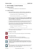
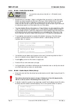
[L1 Sensor 001] Type OPT Level 023
DISCOV Input(2-0):LLL Drift:+00 Mode:03
•
The display shows the following information:
Device Type:
OPT
For a list of the device type abbreviations refer to Table 4 – Device Type
Abbreviations.
Level:
023
(Analogue Value - For sensors; default pre-alarm level is 45, default fire alarm
level is 55. For modules; fault level is 4, normal level is 16 and input activated
level is 64)
Family:
DISCOV (S90, XP95, DISCOVERY)
Input Bits:
LLL
(Digital Input Status for input bits 0-2, H=Logic High, L=Logic Low)
Output Bits:
LLL
Not shown in example, used for multiple output I/O modules only (Digital Output
Status of individual device outputs, H=Logic High, L=Logic Low)
Drift:
00
(Shows the amount of drift compensation employed by the device, range ±16, –
Discovery Only)
Mode:
03
(Shows the operating mode of the device, range 1-5, – Discovery Only)
•
For further information refer to manufacturers data sheets.
5.3.6.1.3 Hochiki Device Information
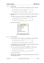
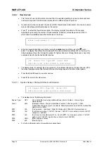
[L1 Sensor 001] Type OPT Level 023
S:096 ZP:061 FP:188 Mode:--
•
The display shows the following information:
Device Type:
OPT
For a list of the device type abbreviations refer to Table 4 – Device Type
Abbreviations.
Level:
023
(Analogue Value - This is a normalised number to account for offsets, calibration
and differences in device type. For sensors; default pre-alarm level is 45, default
fire alarm level is 55. For modules; fault level is 4, normal level is 16 and input
activated level is 64).
S:
096
(Unprocessed raw analogue value returned by the device)
ZP:
061
(Zero Point Value when the device was last calibrated)
FP:
188
(Fire Point Value when the device was last calibrated)
Mode:
--
(Current detection mode enabled in the multi-sensor or multi-mode heat detector)
•
For further information refer to manufacturers data sheets.
5.3.6.1.3.1
Hochiki Multi Input/ Output devices
•
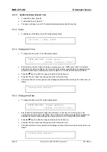
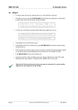
For Hochiki devices with multiple digital inputs and/or outputs, the status of each individual input and
output is shown. The example below shows how the current status of the 1 input and 2 outputs of a
CHQ-B module might be displayed. In the example, the ‘L’ symbol associated with the input indicates
a Logic Low (inactive) condition, the ‘H’ symbol is associated with output ‘a’ (Logic High / Active state)
and the ‘L’ indicates a Logic Low/ inactive output ‘b’ condition.
[L1 Sensor 001] Type I/O Level 000
Inputs(1-1): L Outputs(a-b): HL


