MORLEY-IAS
Dimension
Series
Page 32
Document No. 996-148-000-5, Revision: 5
User Manual
5.3.6.1 View
Devices
•
This function shows the information returned from the selected signalling loop device and is updated
each time it is polled. The information is presented in a different for each protocol.
•
As each device status is ‘viewed’, the device LED for that address is illuminated – this can be a useful
means of identifying individual devices on the system.
•
Press
‘1’
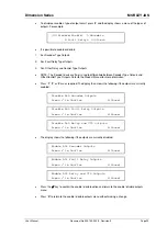
to select the View Devices option. The display prompts for selection of the required
signalling loop, showing the number of loops available, as follows (unless the panel is a DX1e in
which case it immediately shows the first device on the loop):
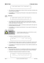
Enter Loop number (1 – n)
•
Enter the required signalling loop number using the
number
keys and then press the
‘
9
’
key to
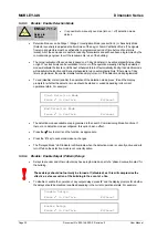
select. The display then shows the information for the device located at address 001 on the loop. The
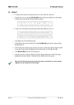
following display shows the information present for System Sensor or Morley-IAS devices – see other
examples below for Apollo and Hochiki devices.
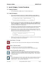
[L1 Sensor 001] Type OPT Level 029%
PW1:149 2:149 3:443 4:0355 5:0445 X:Exit
•
The display shows, for example; the loop number (L1), the address of the device, the type of device (OPT),
the current analogue value of the fire level (29%) and the timing values for the return current pulses.
•
Press
the
Ï
and
Ð
keys to view other devices.
•
Press
‘X’
to return to the View menu.
5.3.6.1.1 System Sensor / Morley-IAS Device Information
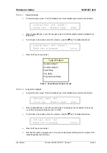
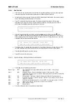
[L1 Sensor 001] Type OPT Level 029%
PW1:149 2:149 3:443 4:0355 5:0445 X:Exit
•
The display shows the following information:
Device Type:
OPT
For a list of the device type abbreviations refer to Table 4 – Device Type
Abbreviations.
Level:
29%
(Analogue Value - This is a normalised number in the range 0% - 100%
irrespective of device type. For sensors; default pre-alarm level is 80%, default fire
alarm level is 100%)
PW1:
149
(Timing pulse – nominally 150uS for Morley-IAS, 300uS for System Sensor)
PW2:
149
(For Sensors; normal = 1xPW1, fire test = 2xPW1. For modules; normal = 1xPW1,
output on = 2xPW1)
PW3:
149
(For Sensors; manufacturer ID, 1x, 2x or 3xPW1. For modules; normal = 1xPW1,
open circuit = 2xPW1, input active or short circuit = 3xPW1)
PW4:
0355
(Raw analogue value)
PW5: 445
(Device
Type)
•
For further information refer to manufacturers data sheets.

