


MORLEY-IAS
Dimension
Series
Page 36
Document No. 996-148-000-5, Revision: 5
User Manual
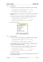
5.3.6.7 View
Voltages
•
Press
‘7’
to select the View Voltages option. The display initially shows the voltage across the battery.
For example:
[U0 VOLTS] BATTERY VOLTS = 23.6
R
:Select X:Exit
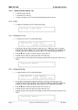
•
Press
the
Ï
and
Ð
keys to view other readings (see table below for full list of signals that can be
viewed and their normal values). For example:
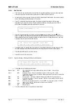
[U0 VOLTS] CHARGER = 26.5
R
:Select X:Exit
•
Press
‘X’
to return to the View menu.
Signal
Description
Value
Normal
Reading /
Range
BATTERY VOLTS
Measurement of the Battery Voltage
Volts
24 (19-28)
CHARGER
Measurement of the Charger Output Voltage
Volts
27 (20-29)
AC POWER
Measurement of the AC Power Input
Volts
240 (190-260)
BATTERY WIRING
Measurement of the battery wiring resistance
1
mOhms 350
(200-500)
MONITORED INPUT 2
Measurement of the input signal condition
Count
500 (480-520)
MONITORED INPUT 1
Measurement of the input signal condition
Count
500 (480-520)
SOUNDER 2
Measurement of the output wiring condition
Count
190 (170-210)
SOUNDER 1
Measurement of the output wiring condition
Count
190 (170-210)
EARTH
Measurement of the earth condition
Count
270 (240-300)
Measurement readings shown are for indicative purposes only.
1
The measurement reading depends also on battery capacity and condition.
Table 7 – Voltage / Analogue Value Readings
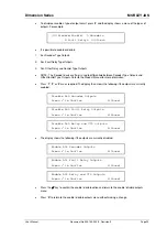
5.3.6.8 View
Version
•
Press
‘8’
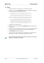
to select the View Versions option. The display shows the part number and version of the
software installed in the panel. It also shows the loop driver protocol and software version loaded into
the signalling loop driver circuit. For example:
[U0 VERSION] System : 993-667-000 3.00
Loop : Apollo 6.02
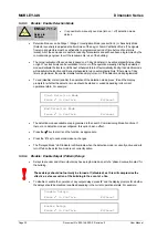
•
Press
‘X’
to return to the View menu.


