


HTR62 Installation and Operating Guide
Rev 1.01
17
Document 900.0341
12/05
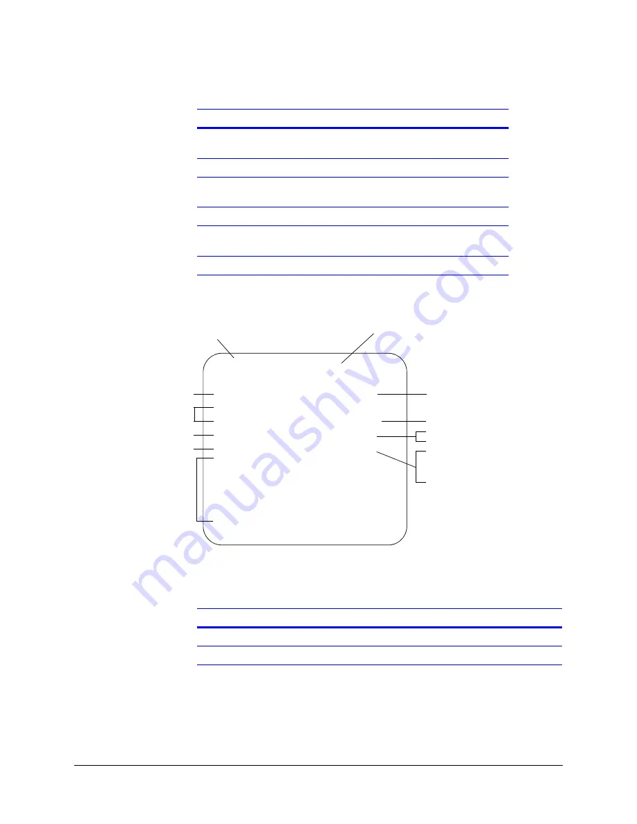
Figure 3-3
Menu Screen, Default Settings Shown
The following symbols are common to all the settings:
The following tables describe where to change the settings on the Menu screen.
Continuous recording loop
(RECM)
Lines 5 and 6
, page
20
Delayed-off time (RECD)
Lines 5 and 6
, page
20
Speed indication (SPD
↓
3600)
Lines 5 and 6
, page
20
Reset system (RES)
Lines 5 and 6
, page
20
Record and display GPS
data
Lines 5 and 6
, page
20
Timers
Lines 7 to 11
,
page 21
Table 3-2
System Default Settings
Setting (cont’d)
To program, see section …
Text line (up to 20 characters)
Reset title line
RECSP = Record speed
Status indicators 1-5
Daily timers
1-5
RECM = Record mode
RECD = Record delay
SPD = Speed calibration
Current date and time
↑
= Parameter is enabled
↓
= Parameter is disabled
For example, Vehicle ID
RES
XXXXXXXXXXXXXXXX
↑
UP RT
01:50:17P JAN/26/05 UP DST
↑
T1BRK
↑
+
↓
T2STP
↑
+
↓
T3TRN
↑
+
↓
T4FSH
↑
+
↓
T5ARM
↑
+
↓
DN SDLY:00
RECSP:EP RECM: RECD:00
SPD
↓
003600 RES MPH DIR
↑
LL
↑
DT1:
↓
12:00A 12:00A
DT2:
↓
12:00A 12:00A
DT3:
↓
12:00A 12:00A
DT4:
↓
12:00A 12:00A
DT5:
↓
12:00A 12:00A
DST = Daylight Saving Time
= System reset
MPH = GPS speed, in miles/hour
DIR = GPS direction
LL = GPS latitude/longitude
SDLY = Start Delay
Symbol
Description
↑
Enables the selected feature or makes the selected trigger active.
↓
Disables the selected feature or makes the selected trigger inactive.
Summary of Contents for HTR62
Page 2: ......
Page 3: ...HTR62 Installation and Operating Guide ...
Page 6: ...Rev 1 01 Document 900 0341 12 05 Contents ii ...
Page 8: ...Rev 1 01 Document 900 0341 12 05 Figures iv ...
Page 10: ...Rev 1 01 Document 900 0341 12 05 Tables vi ...
Page 24: ...Rev 1 01 12 Document 900 0341 12 05 Installation ...
Page 45: ......


