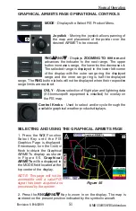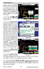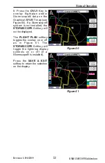
54
Revision 6 Feb/2009
KMD 550/850 FIS Addendum
Normal Operation
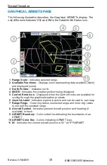
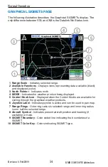
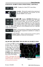
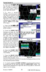
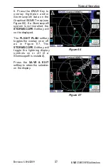
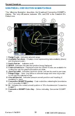
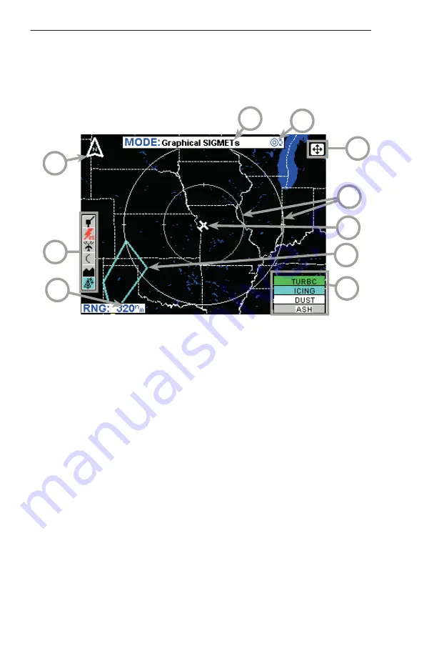
GRAPHICAL SIGMETS PAGE
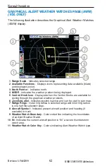
The following illustration describes the Graphical SIGMETs display. The
only difference between VDL and XM is the Datalink Wx Status icon.
1 Ran
g
e
S
cale
- Indic
a
te
s
s
elected r
a
nge.
2 Available Function
s
- Di
s
pl
a
y
s
icon
s
repre
s
enting d
a
t
a
a
v
a
il
ab
le (
b
l
a
ck)
a
nd di
s
pl
a
yed (color).
3
North Pointer
- Indic
a
te
s
north.
4 MODE
- Indic
a
te
s
the we
a
ther prod
u
ct
b
eing di
s
pl
a
yed.
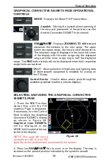
5 Control Knob Icon
- Di
s
pl
a
yed when the Control Kno
bs
a
re
a
v
a
il
ab
le for
cycling thro
u
gh the gr
a
phic
a
l we
a
ther prod
u
ct
s
.
6 Joy
s
tick Label
- Indic
a
te
s
joy
s
tick i
s
a
ctive
a
nd c
a
n
b
e
us
ed to p
a
n m
a
p.
7 Ran
g
e Rin
gs
- O
u
ter ring r
a
di
us
i
s
s
elected r
a
nge
a
nd inner ring r
a
di
us
i
s
one h
a
lf the
s
elected r
a
nge.
8
Aircraft
S
ymbol
- Indic
a
te
s
pre
s
ent
a
ircr
a
ft po
s
ition
a
nd he
a
ding (if
a
v
a
il
ab
le) or tr
a
ck.
9
S
IGMET Boundary
- Color coded line indic
a
ting the
b
o
u
nd
a
rie
s
of
a
S
IGMET.
10
S
IGMET Color Key
- Color
s
indic
a
ting
S
IGMET type.
4
2
9
6
5
1
3
7
8
10

