


30
Mounting and Connection Instructions IDENTLOC Evaluation Unit
0V
ML1
0V
ML2
Shield
+UB
0V
D
Installation area for
dangerous voltages
NO
COM
NC
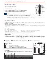
Output relay 1 = Alarm
Rel1
Rel2
Output relay 2 = tamper
Shield
+12 V DC
0 V
Data
to BUS-2
connection
evaluation unit
only master mode
arm / disarm
Input clear
Relay shown in off position
NO
COM
NC
0 V
0 V
1k
12k1
12k1
arm / disarm (ML1)
Input clear (ML 2)
0 V
0 V
ON
1
2
3
4
5
6
DIP switch
8.3
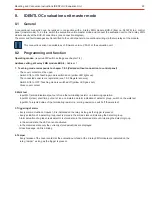
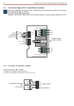
Connection diagram for conventional operation
Observe the Installation- and Security notes in the Mounting and Connection Instructions of the 2-Relay 2-
Input module BUS-2 (Item no. 041220).
Connection variant without VdS approval
Installation note: In BUS-2 master mode, connect additional resistor 1k between data line (data) and +12V DC.
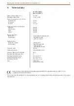
8.3.1
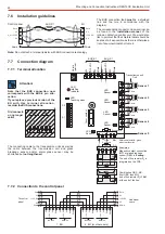
Connection of inputs ML1 and ML2
Detector group inputs (ML1 und ML2):
The wiring of the 2 detector groups are identical.
Connection via potential-free contacts. End of line resistor 12,1k.
Potential-free contacts
from
control panel