


24
Mounting and Connection Instructions IDENTLOC Evaluation Unit
ON
12
ON
12
3
4
56
78
BUS-2
S1
S2
ON
BUS-1
Teach. mode
5-Input Interf.
Normal mode
Normal mode
IDENTLOC EU
Master mode
BUS-2/1
address
32
16
8
4
2
1
Valence
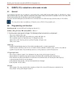
7.
IDENTLOC evaluation unit
2/BUS- ,
no. 032211.17
BUS-
1 Item
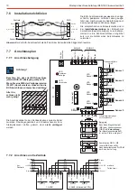
7.1
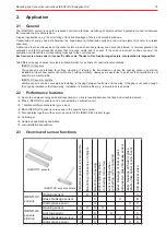
General
Depending on the application and control panel technology, the evaluation unit can be operated either at BUS-2 or BUS-1.
Indication states are transmitted exclusively via the BUS interface to the control panel irrespective of the employed BUS
system.Select the desired BUS system using the DIP switch in the EU.
Compatibility:
When operating with BUS-1, the EU is fully compatible with the previous version EU BUS-1, Item no. 032211.
It is therefore possible to upgrade an existing system or to replace a previous EU.
(Exception: Pin allocation of the BUS connection. See Chapter 7.7.1 "Terminal allocation").
Variant:
As of firmware version V03.01 of the evaluation unit, a conventional connection can be realized in conjunction
with a 2-relay 2MG module BUS-2 (Item no. 041220) to a control panel (master mode).
7.2
BUS-2 function
Operating modes:
(required DIP-switch setting see 7.4.1)
1) Compatibility mode "
". (Standard operating mode with control panel software up to V09.xx)
5-Input Interface
2)
mode (control panel software from V10.xx, EU sofware from V02.xx required)
"IDENTLOC"
Additional Functions:
- G
lass breakage sensor-function can be disactivated (via control panel programming)
- Run "Teaching mode" from control panel. Therefore the housing of the EU is closed.
- Firmware update via BUS-2
If the BUS-2 user is incorporated in the control panel programming, the EU is automatically identified as a 5-Input Interface or
IDENTLOC EU (as programmed).
The EU occupies one address. The individual sensors are identified via BUS communication.
7.3
BUS-1 function
Program the EU as a "Logic detector".
There are two possibilities of transmitting data:
7.4
Programming
The DIP switches S1/1 to S1/7 and S2/2 are only queried during initialization (when operating voltage is applied). The
setting of these switches only functions when
!
de-energized
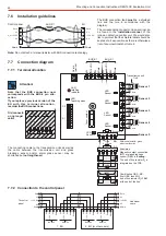
The DIP switch S1/8 (switching between teaching mode/normal mode) is queried
cyclically and can be reset at all times during operation.
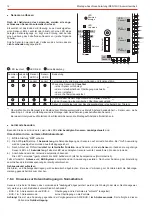
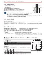
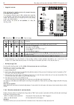
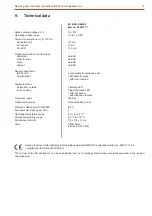
7.4.1
Operation at BUS-2
- Activate BUS-2 operation:
DIP switch
iposition
S2/2
ON
Unit normal mode:
DIP switch
iposition
S1/7
OFF
Unit master mode:
DIP switch
iposition
S1/7
ON (only with 2-relay 2MG module)
- Select BUS-2 operating mode:
5-Input Interface:
S2/1 OFF
IDENTLOC EU:
S2/1 ON
1. 1-Address mode
All sensor data are transmitted together to
at BUS-1.
1 address
The control panel
the individual sensors.
cannot identify
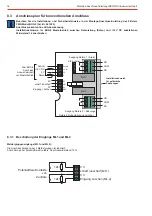
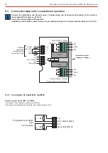
2. 5-Address mode
Sensor data are transmitted separately to
at BUS-1.
5 addresses
As each sensor has its own address, the central control until can
unambiguously identify
each sensor.
Only the lowest address is set at the EU. The 4 consecutive addresses are
allocated automatically by the EU. (See example on right).
The cover contact in this operating mode is automataically allocated to the
lowest address.
Example 5 address mode:
4
Sensor 1
5
Sensor 2
6
Sensor 3
7
Sensor 4
8
Sensor 5
9
Programmed address
Automatically
allocated addresses
Next free address