


COMPONENT MAINTENANCE MANUAL
00001059
SUBTASK 21-22-91-410-003-A01
For PNR 00001059 Amdt B
(5)
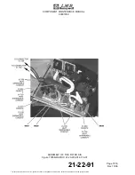
Installation of the Control Board (01-330A)
(Ref. IPL Fig. 01)
(Ref. Fig. 7004)
(a)
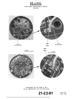
Put the control board (01-330A) in position in the control board support (01-320A).
(b)
Apply a layer of adhesive material (M38B) on the thread of the screws (01-340).
(c)
Attach the control board (01-330A) to the control board support (01-320A) with the three
washers (01-350) and the three screws (01-340) .
(d)
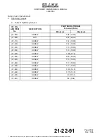
Torque the screws (01-340) to the specified value (Ref. TASK 21-22-91-820-802-A01).
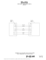
(e)
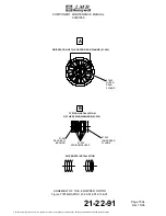
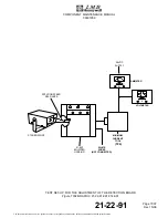
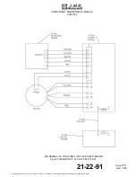
Solder the other end of the yellow wire (01-790) on the control board (01-330A) with
solder material (M60X) (Ref. Fig. 7004).
(f)
Clean the solder and apply a layer of varnish SCC3 (MXXD).
(g)
Bond the yellow wire (01-790) on the control board (01-330A) with a spot of adhesive
material (M81B) close to the solder.
(h)
Put the Control S/A (01-290A) in position on the tie-rods (01-440).
(i)
Apply a layer of adhesive material (M38B) on the thread of the three tie-rods (01-440).
(j)
Attach the Control S/A (01-290A) with the three washers (01-310) and the three nuts
(01-300).
SUBTASK 21-22-91-410-003-B01
For PNR 00001059 Amdt C
(6)
Installation of the Control Board (01-330B)
(Ref. IPL Fig. 01)
(Ref. Fig. 7004)
(a)
Put the control board (01-330B) in position in the control board support (01-320B).
(b)
Apply a layer of adhesive material (M38B) on the thread of the screws (01-340).
(c)
Attach the control board (01-330B) to the control board support (01-320B) with the three
washers (01-350) and the three screws (01-340) .
(d)
Torque the screws (01-340) to the specified value (Ref. TASK 21-22-91-820-802-A01).
(e)
Solder the other end of the yellow wire (01-790) on the control board (01-330B) with
solder material (M60X) (Ref. Fig. 7004).
(f)
Clean the solder and apply a layer of varnish SCC3 (MXXD).
(g)
Bond the yellow wire (01-790) on the control board (01-330B) with a spot of adhesive
material (M81B) close to the solder.
21-22-91
Page 7013
Dec 15/06
The document reference is online, please check the correspondence between the online documentation and the printed version.