


COMPONENT MAINTENANCE MANUAL
00001059
SUBTASK 21-22-91-430-001-A01
(2)
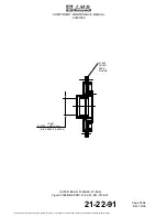
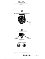
Assembly of the Detection Rotor (01-510) and of the Detection Board (01-480)
(Ref. IPL Fig. 01)
(a)
Apply a layer of adhesive material (M38B) on the threaded part of the screw (01-490).
CAUTION: IF YOU INSTALL THE DETECTION ROTOR (01-480) THAT YOU REMOVED ON
DISASSEMBLY, MAKE SURE THAT YOU PUT IT IN THE SAME POSITION.
(b)
Attach the detection rotor (01-480) to the rear side of the rotor (01-630) with the screw
(01-490) and the lockwasher (01-500).
(c)
Torque the screw (01-490) to the specified value (Ref. TASK 21-22-91-820-802-A01)
CAUTION: IF YOU INSTALL THE DETECTION BOARD (01-450) THAT YOU REMOVED ON
DISASSEMBLY, MAKE SURE THAT YOU PUT IT IN THE SAME POSITION.
(d)
Put the detection board (01-450) in position against the outer rear flange (01-560).
(e)
If you install a new detection rotor (01-480) or a new detection board (01-450), temporarily
attach the detection board (01-450) with three screws (01-460) and three washers
(01-470) and do the adjustment procedure (Ref. SUBTASK 21-22-91-820-001-A01).
NOTE:
Do not apply adhesive material (M38B) and do not tighten the screws (01-460) at
this time.
(f)
If you install the detection rotor (01-480) and the detection board (01-450) that you
removed on disassembly:
1
Apply a layer of adhesive material (M38B) on the threaded part of the screws
(01-460).
2
Attach the detection board (01-450) with the three screws (01-460).
3
Torque the screws (01-460) to the specified value (Ref. TASK 21-22-91-820-802-A01).
SUBTASK 21-22-91-820-001-A01
(3)
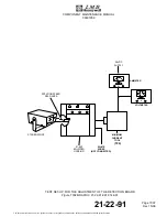
Adjustment of the Detection Board (01-450)
(Ref. IPL Fig. 01)
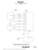
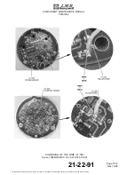
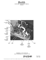
(Ref. Fig. 7002)
(a)
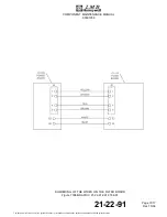
Install the equipped housing assembly (01-640) on the test set-up (Ref. Fig. 7002).
NOTE:
Connect each wire to the related color on the minimum current tool (T06).
(b)
Apply a 28 VDC voltage to the minimum current tool (T06).
(c)
Let the motor turn clockwise under 28 VDC during 10 min.
(d)
With the stroboscope, measure the maximum rotation speed on the shaft of the rotor
(01-630).
(e)
With the ammeter connected between the 28 VDC source and the minimum current
tool (T06), measure the minimum current.
21-22-91
Page 7005
Dec 15/06
The document reference is online, please check the correspondence between the online documentation and the printed version.