


COMPONENT MAINTENANCE MANUAL
00001059
5
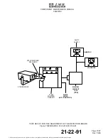
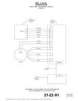
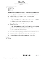
Attach the power board (01-370) to the drain (01-430B) with three screws (01-380),
six screws (01-390), fifteen washers (01-400) and six nuts (01-410).
6
Torque the screws (01-380) and (01-390) to the specified value (Ref. TASK
21-22-91-820-802-A01).
(h)
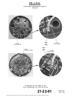
Shrink three 20 mm (0.787 in) lengths of heat shrinkable conduit (01-770) on these wires:
– The two stator probe white wires,
– The yellow and the black wires of the detection board,
– The orange and the red wires of the detection board.
(i)
Shrink three 25 mm (0.984 in) lengths of heat shrinkable conduit (01-780) on each pair
of stator phases wires grouped by color.
(j)
Group all the wires in three bundles and shrink three 35 mm (1.378 in) lengths of heat
shrinkable conduit (01-760).
(k)
Put the five detection board wires and the two stator probe wires together in a 50 mm
(1.97 in) length of heat shrinkable conduit (01-760).
(l)
Put the six stator wires together by pairs and by colors in three 35 mm (1.378 in) lengths
of heat shrinkable conduit (01-760).
(m)
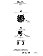
Put all the wires through the power board (01-370) by their related holes.
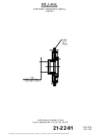
CAUTION: FOR PNR 00001059 AMDT C, MAKE SURE THAT THE DRAINAGE HOLE OF
THE DRAIN (01-430B) IS LOCATED AT THE BOTTOM.
(n)
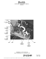
Put the drain/power board assembly in position in the equipped housing (01-640).
NOTE:
Pull the wires which go to the filter board through the dedicated hole of the
equipped housing (01-640).
(o)
Install a 80 mm (3.15 in) length of conduit (01-270) on the wires which go to the filter
board and push it in the power module.
(p)
Apply a layer of adhesive material (M38B) on the thread of the screw (01-220).
(q)
Attach the cover (01-210) on the grommet (01-240) with the screw (01-220) and the
washer (01-230).
(r)
Torque the screw (01-220) to the specified value (Ref. TASK 21-22-91-820-802-A01).
(s)
Shrink three 15 mm (0.590 in) lengths of heat shrinkable conduit (01-760) on each pair of
stator wires and push them in the holes.
NOTE:
Let between 2 and 3 mm (0.0787 to 0.1181 in) of heat shrinkable conduit
(01-760) over the power board (01-370).
(t)
Carefully pull all the wires through the holes.
21-22-91
Page 7009
Dec 15/06
The document reference is online, please check the correspondence between the online documentation and the printed version.