


13
The standard models have one sensor, that measures the
resistance against ground (motor housing). The sensor is
connected to the pump cable, the wire-end is marked S
1
(see fig. 1).
The explosion-proof models have two sensors between
which the resistance is measured. The sensors are con-
nected to the pump cable, the wire-ends are marked S
1
and S
2
(see fig. 1).
The sensor(s) must be connected to a tripping unit, which
is connected to the safety circuit of the pump controller.
For explosion-proof models there has to be an intrinsi-
cally-safe relay. The tripping unit should have an adjust-
able sensitivity of 0 to 100 k
Ω
, standard setting is approx.
50 k
Ω
.
6.5. Check of Direction of Rotation
1Ph-pumps do not require any check, as they always run
with the correct direction of rotation.
3Ph-pumps must be checked for correct direction of rota-
tion before start-up. On original HOMA control boxes a
control-light is illuminated, if the direction is not correct.
With smaller pumps the direction of rotation may be
checked by watching the start-jerk. Put the pump vertical
on the ground and lift one edge. Start the motor. Viewed
from above, the unit must jerk anti-clockwise, as the cor-
rect direction of rotation is clockwise.
With bigger pumps the check may also be
done by watching the rotation of the impeller
through the discharge or the suction inlet. With
pumps already installed, the check may be
done by comparing head (pump pressure) and
flow (quantity of water) at different direction of
rotation. The direction that gives higher head
and flow is the correct one. If the direction of
rotation is wrong, interchange two of the
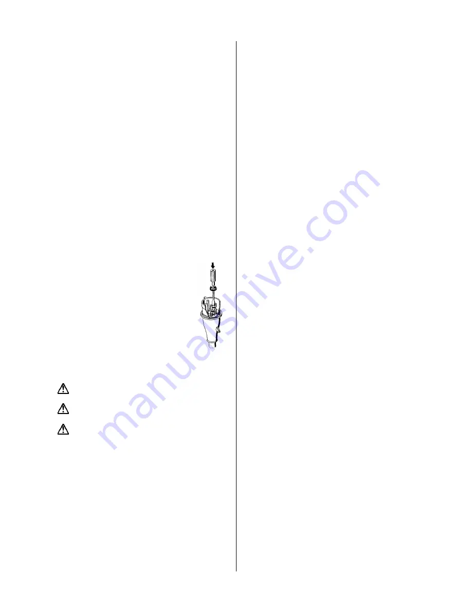
phases of the electric power supply. Using an
original HOMA control box with CEE-plug, this
may be done by a 180° turning of the small
round pole socket at the plug-end with a
screwdriver.
7. Installation
Pay attention to the maximum depth of immersion
(see pump label).
If the pump is installed in a sump, the sump opening
must be covered with a tread-safe cover after installation.
The operator has to prevent damage through the
flooding of rooms caused by defects of the pump through
the use of appropriate measures (e.g. installation of alarm
units, backup pump or the like).
7.1. Submerged Base Stand Installation
For CH 446 pumps a separate ring base stand, which is
available as an accessory must be fixed at the bottom of
the pump. Fix a 90° elbow to the pump discharge. The
pump may be installed with a flexible discharge hose or a
rigid pipe, non-return valve and isolating valve. If a flexible
hose is used, make sure that it does not buckle.
Fix a rope or a chain to the pump handle and lower the
pump into the liquid. If the pump is installed on muddy
ground, support it on bricks to prevent if from sinking in.
7.2. Submerged Installation with Auto-Coupling
Permanent installation of the pumps can be done on a
stationary auto-coupling. The following instructions refer
to the use of the original HOMA system.
•
Place the auto-coupling base unit on the bottom of the
pit. Use a plumb line to fix the correct position of the
guide rail bracket on the inside of the pit cover. Drill
mounting holes and fasten the guide rail bracket provi-
sionally with 2 screws.
•
Put the auto-coupling base unit in the exact position and
fasten with expansion bolts to the pit bottom. If the bot-
tom is uneven, the base unit must be supported to be in
horizontal position.
•
Assemble the discharge line in accordance with the
generally accepted procedures and without exposing
the line to distortion or tension.
•
Insert the guide rails in the rings of the auto-coupling
base and adjust the length of the rails by cutting them
accurately to the guide rail bracket.
•
Unscrew the provisionally fastenend guide rail bracket,
fit it on top of the guide rails and fasten it to the pit
cover. Make sure that the guide rails do not have any
axial play, as this would cause noise during pump op-
eration.
•
Clean out debris from the pit before lowering the pump
into operation position.
•
Fit the coupling flange at the discharge of the pump.
Make sure that the rubber profile-seal is properly fixed
to the flange and will not fall off when the pump is
lowered into the pit. Slide the guide bar of the coupling
flange between the guide rails and lower the pump into
the pit by means of a chain secured to the pump han-
dle. When the pump reaches the auto coupling base
unit, it will automatically connect tightly.
•
Hang up the end of the chain to a suitable hook at the
top of the pit.
•
Adjust the length of the motor cable, so that it is not
damaged during the pump operation. Make sure that
the cables are not sharply bent or pinched.
7.3 Automatic Floatswitch Control
The pumps may be supplied with floatswitch level control-
lers. They start and stop the pump according to the liquid
level in the pit.
The difference in level between start and stop must be
adjusted by adjusting the free swinging length of the ca-
ble between the floatswitch and the cable fastening.
Long cable end: Large difference in level.
Short cable end: Small difference in level.
The stop level must be adjusted in such a way, that the
pump stops before the liquid level is lowered below the
top of the pump volute.
The start level must in any case be below the bottom of
the liquid inlet pipe of the pit.
The high alarm level, if a separate floatswitch for that is
installed, should be adjusted approx. 10 cm above the
start level, in any case it must be below the bottom of the
liquid inlet pipe of the pit, so that the start level must be
adjusted accordingly.
Note:
Only the proper adjustment and fixing of the
floatswitch cable will guarantee a reliable pump operation.
After any modification of the floatswitch adjustment the
function must be checked by a test-run of the pumps.


