


7
Adres producenta/ Adresse des Herstellers/ Manufacturer’s Address/ Адрес производителя
GTV Poland Sp. z o.o. Sp. k., ul. Przejazdowa 21, 05-800 Pruszków
EN
USER’S MANUAL
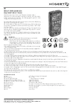
MULTIMETER HT1E603
Thank you for purchasing our product. Manufactured to a high standard, this
product will, if used according to these instructions, and properly mainta-
ined, give you years of trouble free performance.
This manual contains safety information, operation, specifi cations and ma-
intenance of the meter.
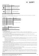
The device is used to measure DC and AC voltage, current and resistance,
continuity measurement, diodes and temperature, etc.
The meter has functions of polarity indication, data storage, value retention,
overrange indication, Auto Power Off, NCV and RMS.
It is produced according to EN61010-1 for electronic measuring instruments
with surge category (CAT III 600 V) and pollution degree 2.
WARNING
To avoid electric shock or personal injury, observe the following
rules:
• Check the housing before using the meter. Do not use when
the meter or its housing is damaged. Look for cracks. Note
the insulation around the joints.
• Check the test leads for damaged insulation or exposed wires.
• Do not measure a voltage higher than the rated voltage specifi ed on the
indicator.
• The rotary switch must be set in the correct position and do not change
the range during measurement.
• When voltages exceed 60 V for AC and 30 V for DC, special care must be
taken against the danger of electric shock.
• Use the appropriate terminals, functions and range for the measure-
ment.
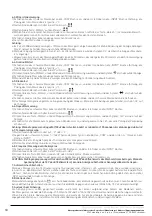
• Do not use or store the meter in an environment with high temperature, humidity, explosives, fl ammable materials,
high magnetic fi eld.
• Disconnect the power supply to the circuit and discharge the capacitors before testing resistance, continuity or diodes.
• Replace the battery as soon as the battery indicator shows a low charge. With a low battery, the meter can generate false readings.
• Disconnect the cables and switch off the meter before opening the housing.
• No changes must be made to the design and construction of the meter.
• Use a soft cloth and mild detergent for cleaning. Do not use abrasives or solvents
• The meter is suitable for indoor use.
• Turn the meter off when not in use, and remove the battery when not in use for a long time
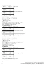
TECHNICAL DATA
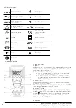
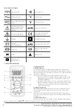
Display:
LCD, updated every 2 seconds
Screen size:
55 x 31 mm
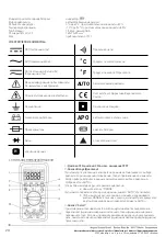
Polarity marking:
„–” displays automatically
Overrange indication:
„OL” displays
Low battery indicator:
displays „
”
Range selection:
automatic or manual
Operating temperature:
0°C to 40°C, humidity not less than 80% RH
Storage temperature:
-10°C to 50°C, relative humidity not less than 85%
Battery type:
1,5 V x 3, type AAA
Dimensions:
145 x 70 x 35 mm
Weight:
approx 157 g


