background image

12

 Adres producenta/ Adresse des Herstellers/ Manufacturer’s Address/ Адрес производителя 

GTV Poland Sp. z o.o. Sp. k., ul. Przejazdowa 21, 05-800 Pruszków

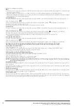
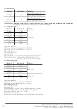
   6) Read the reading on the display.

   Note:

   a.  In the case of resistance measurements > 1MΩ, the meter may take several seconds to stabilize the reading. This is normal for high 

resistance measurements. 

   b.  When the input is not connected, i.e. in an open circuit, the „OL” symbol will be displayed as an overrange indicator. 

   c.  Before measuring the resistance in a circuit, make sure that the circuit being tested has been disconnected from the power supply 

and all capacitors are completely discharged. 

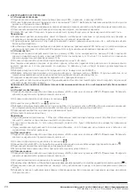
   6-4. Continuity test

   1) Connect the black lead to the COM socket and the red lead to INPUT socket (Note: The polarity of the red lead is positive „+”).

   2) Set the range switch to „ 

   3) Press the Select button to select the continuity measurement mode and the symbol  „ ” will appear as an indicator.

   4) Connect test leads to the measured circuit.

   5) If the circuit resistance is lower than about 30 Ω, the built-in buzzer sounds.

   6-5. Diode test

   1) Connect the black lead to the COM socket and the red lead to INPUT socket (Note: The polarity of the red lead is positive „+”).

   2) Set the range switch to „ 

”.

   3) Press the Select button to select the continuity measurement mode and the symbol „

” will appear as an indicator.

   4) Connect the red lead to the anode of the tested diode and the black lead to the cathode.

   5)  The meter will show the approximate conduction voltage of the diode. If connections are reversed, „OL”  

will appear on the display. 

   6-6. Capacity measurement:

   1) Connect the black lead to the COM socket and the red lead to the IMPUT socket.
   2) Set the range switch to „

   3) Press the Select button to select the continuity measurement mode and the symbol „mF” will appear as an indicator.

   4) Connect the test leads to the measured capacitor and make sure that the connection polarity is maintained.

   Note: When the measured capacity exceeds 100uF, it takes at least 10 seconds for the reading to be stable.

   6-7. Temperature measurement

   1) Set the range switch to „

˚

C” or „

˚

F”.

   2) Insert the black („-”) K-type thermocouple plug into the COM socket and the red („+”) plug into the IMPUT socket.

   3) Carefully touch the thermocouple tip to the object being measured.

   4) Wait a moment, read the reading on the display.

   6-8. Frequency / measurement of the operating cycle

   1) Connect the black lead to the COM socket and the red lead to the IMPUT socket.

   2) Set the range switch to „Hz%”.

   3) Press the Select button to select „Hz” or „work cycle” mode

   4) Connect the test leads to the measured source or circuit.

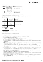
   NOTICE:  The input voltage should be between 200 mV and 10 V rms AC. If the voltage is higher than 10 V rms, the reading may 

be out of the accuracy range.

   7. Automatic breaker

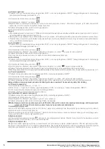
    If the meter is not used for about 15 minutes, it will power off automatically. To turn it on again, simply turn the range switch or 

press the button.

    In the off state, press the Select button. Turn the range switch, you can cancel the automatic switch-off function, the „APO” symbol 

disappears from the LCD display.

   8. Battery replacement

    If the display shows „

”, that means the battery needs to be replaced. Remove the screws and open the rear housing, replace 

the battery with new ones (size AAA, 1.5 V x 3 or equivalent). 

   9. Fuse replacement

    The fuse rarely needs to be replaced and is almost always burned out due to operator error. The meter uses the fuse:  

F1: 500 mA / 600 V i F2: 10 A / 600 V fast operation. To replace the fuses, open the rear cover of the meter, replace the damaged 

fuse with a new one of the specified values. Reinstall the battery cover and lock it.

Summary of Contents for HT1E603

Page 1: ...eni zakresu podczas pomiaru Przy napi ciu przekraczaj cym 60 V dla pr du przemiennego i 30 V dla pr du sta ego nale y zachowa szczeg ln ostro no przed niebezpiecze stwo pora enia pr dem U yj odpowiedn...

Page 2: ...jest w trybie auto matycznego zasi gu wy wietla si AUTO Aby wej i wyj z trybu r cznego zakresu a Naci nij przycisk RANGE miernik przechodzi w tryb r cznego zakresu a symbol AUTO ga nie b Aby wyj z tr...

Page 3: ...iar w pr du 200mA 5 SPECYFIKACJA 5 1 Napi cie pr du sta ego DC Auto ranging Zakres Rozdzielczo Dok adno 400 mV 0 1m V 0 8 odczytu 5cyfr 4 V 1 mV 0 8 odczytu 3 cyfry 40 V 10 mV 400 V 100 mV 600 V 1 V 1...

Page 4: ...A 400 mA i 10 A 400 mV 5 5 Nat enia pr du przemiennego AC Zakres Rozdzielczo Dok adno 400 A 0 1 A 1 5 odczytu 8cyfr 4000 A 1 A 40 mA 10 A 400 mA 100 A 4 A 1 mA 1 5 odczytu 8cyfr 10 A 10 mA Ochrona prz...

Page 5: ...go przewodu zostanie wskazana podczas wykonywania pomiaru pr du sta ego Uwaga a W ma ym zakresie miernik mo e wy wietla niestabilny odczyt gdy przewody pomiarowe nie zosta y pod czone do mierzonego ob...

Page 6: ...dy Je lipo czeniazostan odwr cone nawy wietlaczupojawisi OL 6 6 Pomiar pojemno ci 1 Pod cz czarny przew d pomiarowy do gniazda COM a czerwony do gniazda INPUT 2 Ustaw prze cznik zakresu w pozycji 3 Na...

Page 7: ...in the correct position and do not change the range during measurement When voltages exceed 60 V for AC and 30 V for DC special care must be taken against the danger of electric shock Use the appropri...

Page 8: ...ter is in automatic range mode AUTO is displayed To enter and exit manual range mode a Press the RANGE button the meter goes into manual range mode and the AUTO symbol goes out b To exit manual mode p...

Page 9: ...nts except for current measurements 200mA 5 SPECIFICATION 5 1 DC voltage Auto ranging Range Resolution Accuracy 400mV 0 1mV 0 8 reading 5 digits 4V 1mV 0 8 reading 3 digits 40V 10mV 400V 100mV 600V 1V...

Page 10: ...A 400 mA i 10 A 400 mV 5 5 AC current amperage Range Resolution Accuracy 400 A 0 1 A 1 5 reading 8 digits 4000 A 1 A 40 mA 10 A 400 mA 100 A 4 A 1 mA 2 0 reading 10 digits 10 A 10 mA Overload protect...

Page 11: ...to the circuit being measured This is normal and will not affect measurements b In manual range mode when the meter shows the OL overrange symbol select a higher range c To avoid damage to the meter...

Page 12: ...ontinuity measurement mode and the symbol mF will appear as an indicator 4 Connect the test leads to the measured capacitor and make sure that the connection polarity is maintained Note When the measu...

Page 13: ...eich Bei Spannungen ber 60 V f r Wechselstrom und 30 V f r Gleichstrom ist besondere Vorsicht einzuhalten im Hinblick auf die Stromschlaggefahr Verwenden Sie die entsprechenden Klemmen Funktionen und...

Page 14: ...it t messen Wenn das Messger t sich im Modus des automatischen Bereichs befindet wird AUTO angezeigt Um in und aus dem Modus des manuellen Bereichs zu wechseln a Dr cken Sie die Taste RANGE das Messge...

Page 15: ...e COM f r das schwarze negative Messkabel 11 Buchse INPUT SteckverbinderdesrotenMesskabelsf ralleMessungenmitAusnahmederStromst rkemessungen 200mA 5 SPEZIFIKATION 5 1 Gleichspannung DC Auto ranging Be...

Page 16: ...400 mA und 10 A 400 mV 5 5 Wechselstromst rke AC Bereich Aufl sung Genauigkeit 400 A 0 1 A 1 5 Anzeige 8 Stellen 4000 A 1 A 40 mA 10 A 400 mA 100 A 4 A 1 mA 2 0 Anzeige 10 Stellen 10 A 10 mA berladun...

Page 17: ...ezeigt Achtung a Im kleinen Bereich kann das Messger t instabile Werte anzeigen wenn die Messkabel nicht am gemessenen Stromkreis angeschlossen wurden Dies ist normal und wirkt sich nicht auf die Mess...

Page 18: ...rze Messkabel an die COM Buchse an und das rote Kabel an die INPUT Buchse 2 Stellen Sie den Bereichsschalter in der Position ein 3 Dr cken Sie die Taste W hlen um den Modus der Kontinuit tsmessung zu...

Page 19: ...9 Adres producenta Adresse des Herstellers Manufacturer s Address GTV Poland Sp z o o Sp k ul Przejazdowa 21 05 800 Pruszk w RU HT1E603 hFE 3 3 4 3999 EN61010 1 CAT III 600 60 30 hFE 3999 2 55 x 31 OL...

Page 20: ...erstellers Manufacturer s Address GTV Poland Sp z o o Sp k ul Przejazdowa 21 05 800 Pruszk w 0 C 40 C 80 10 C 50 C 85 1 5 x 3 AAA 145 70 35 157 DC AC C DC AC F AUTO APO H 4 1 3 3 4 3999 2 Range AUTO a...

Page 21: ...o Sp k ul Przejazdowa 21 05 800 Pruszk w 4 HOLD HOLD 5 H 2 2 5 Max Min 6 7 Hz Hz HZ ACV 8 Function Range 9 200 10 10 COM 11 INPUT 200 5 1 23 5 80 5 1 400 0 1 0 8 5 4 1 0 8 3 40 10 400 100 600 1 1 0 5...

Page 22: ...4 150 C 1370 C 2 5 4 40 2000 F 1 F 40 F 302 F 2 5 4 302 F 2000 F 2 5 4 5 4 400 0 1 1 2 8 4000 1 40 mA 10 400 mA 100 4 A 1 10 A 10 F0 5 A 600 V 4 10 F10 A 600 INPUT 200 10 5 10 15 400 40 4 40 4000 400...

Page 23: ...o o Sp k ul Przejazdowa 21 05 800 Pruszk w 5 6 400 0 1 1 5 3 4 K 1 40 K 10 400 K 100 4 M 1 K 40 M 10 K 0 25 250 5 7 1 5 30 0 5 250 50 100 100 5 8 40 10 8 10 400 100 5 5 4u 1 40 10 100 2 100 5 10 5 50...

Page 24: ...V Poland Sp z o o Sp k ul Przejazdowa 21 05 800 Pruszk w 6 6 1 1 COM INPUT 2 V lub V RANGE 3 4 5 OL 600 600 6 2 1 COM 200 INPUT 200 10 10 2 3 SELECT 4 RANGE 5 6 OL 6 3 1 COM INPUT 2 3 SELECT 4 RANGE 5...

Page 25: ...Przejazdowa 21 05 800 Pruszk w 6 6 1 COM INPUT 2 3 SELECT mF 4 100 10 6 7 1 C F 2 K COM INPUT 3 4 6 8 1 COM INPUT 2 Hz 3 SELECT Hz 4 200 10 10 6 9 NCV DT132B 1 NCV 2 NCV 3 NCV NCV 4 30 1000 NCV NCV 6...

Page 26: ...26 Adres producenta Adresse des Herstellers Manufacturer s Address GTV Poland Sp z o o Sp k ul Przejazdowa 21 05 800 Pruszk w...

Page 27: ...27 Adres producenta Adresse des Herstellers Manufacturer s Address GTV Poland Sp z o o Sp k ul Przejazdowa 21 05 800 Pruszk w...

Page 28: ...28 Adres producenta Adresse des Herstellers Manufacturer s Address GTV Poland Sp z o o Sp k ul Przejazdowa 21 05 800 Pruszk w...

Reviews: