arm, to a hole that is as close to 17/32" [13mm] as possible).
Secure the connector with a nylon retainer.
❏
7. Place the servos in the servo tray as shown in the photo
at step 5. Drill 1/16" [1.6mm] holes through the servo tray for
mounting the servos. Mount the servos in the tray with the
screws that came with the servos.
❏
8. Remove the screws and the servos. “Harden” the holes in
the servo tray with a drop of thin CA in each hole. Allow to fully
harden, then reinstall the servos with the screws.
❏
9. Insert the nose-steering pushrod into the screw-lock pushrod
connector on the rudder servo.
❏
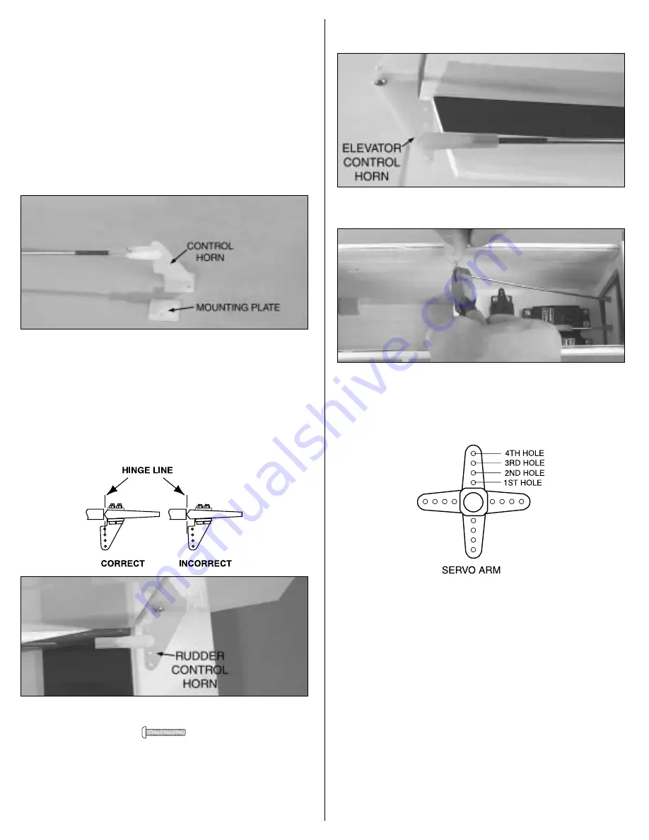
10. Thread a nylon clevis onto a 36" [910mm] wire pushrod
twenty full turns. Cut the mounting plate from a control horn,
then connect the clevis on the pushrod to the third hole from
the bottom of the horn. Cut 9 inches [230mm] from the
unthreaded end of the pushrod. This will be the elevator
pushrod. Prepare the rudder pushrod the same way, only
connect the clevis to the second hole from the bottom of the
control horn. Guide the pushrods through the respective tubes
in the fuselage.
#2-56 x 1/2" [13mm] screw
❏
11. Position the rudder control horn on the rudder so the
clevis holes in the horn are in line with the hinge gap as shown
in the sketch. Using the mounting holes in the control horn as
a template, drill 3/32" [2.4mm] holes through the rudder for
mounting the horn. Mount the horn with two 2-56 x 1/2" [13mm]
screws and the mounting plate.
❏
12. Mount the elevator control horn to the elevator using the
same procedure described in the previous step.
❏
13. The same way you did for the aileron pushrods, use a
felt-tip pen to mark the elevator and rudder pushrods where
they cross the holes in the servo arms. Disconnect the clevises
from the control horns, then make 90° bends in the pushrods
at the marks.
❏
14. Enlarge the holes in the elevator and rudder servo
arms with a #48 or 5/64" [2mm] drill or a hobby knife so the
pushrods will fit. Connect the elevator pushrod to the third hole
in the elevator servo arm (or 17/32" [13mm] from center) and
the rudder pushrod to the third hole on the rudder servo arm
(or 17/32" [13mm] from center). Secure the pushrods with a
Faslink. Cut off the excess wire 1/16" [2mm] above the Faslink,
then connect the servo arms to the servos.
❏
15. Adjust the clevises on the back of the pushrods so the
elevator and rudder will be centered, then fit them onto the
control horns. The clevis on the elevator pushrod should be in
the third hole from the base of the horn and the clevis on the
rudder pushrod should be in the second hole from the base of
the horn.
Now it’s time to glue…
❏
16. With the pushrods connected to the servos, use medium
CA to glue the pushrod brace to the back of the former and to
14


