Hobbico Sturdy Birdy II Instruction Manual Download Page 9

approximately 1" from the edge. The middle
hinge is in the center and the other two hinges
are centered between the outer hinges and the
middle hinge. These hinge locations are not
critical, but proper placement makes it easier
to find the slots after the parts are covered.
Cut the slots for the hinges and test fit the
stabilizer and the elevator together to check for
proper alignment between the two parts.

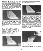
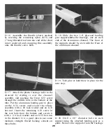
D 17. Use some thick CA to glue the 1/16"
plywood doubler in place on the stabilizer. This

side is now the bottom of the stabilizer. Use
a ruler to get this piece centered as close as
possible. Use a drafting triangle or carpenter's
square to draw a line perpendicular to the
stabilizer trailing edge and through the center of
the stabilizer to the point where the leading
edges meet.

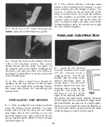
D 18. Use a pencil and a rubber band to hold
the stabilizer in place as shown in the photo.

Sight down the bottom of the channel and line
the stabilizer up with the channel (using the
line you just drew). When you are satisfied with
the alignment, draw a line down both sides of

the channel on the top of the stabilizer.

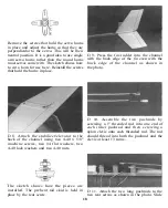
D 19. Remove the pencil and rubber band.

With the stabilizer centered over the lines, drill

two 1/8" holes through the stabilizer using the
holes in the channel as a guide. The trailing
edge of the stabilizer should be slightly past
the end of the channel.

D 20. Use a sanding block with some fine
sandpaper to round off the leading edges,

trailing edge and the tips as you did for the
fin and rudder. Also sand the top and bottom
surfaces smooth. This completes the basic
assembly of the stabilizer and elevator. The
control horn and the hinges will be installed
after the tail is covered.

9

Summary of Contents for Sturdy Birdy II

Page 1: ...n of a responsible adult If not handled correctly this model is capable of inflicting serious bodily harm It is your responsibility and yours alone to assemble this model correctly properly install al...

Page 2: ...Doubler 1 ARF1F04 1 4 Plywood Firewall 1 ARF1F05 1 4 Ply Landing Gear Supports 2 ARF1F06 Pushrod Holder 3 4 x 1 2 x 1 1 ARF1S04 1 16 Plywood Stabili er Doubler 1 DOWEL030 1 4 x3 1 2 Dowel 4 ARF2A04 S...

Page 3: ...udes a subscription to MODEL AVIATION magazine which has a monthly listingofthe latestnews in model aviation Insurance is the most important advantage of the AMA membership If your model hits someone...

Page 4: ...difficult to fly at low speeds The engine mount provided with the STURDY BIRDY II will fit most 20 30 engines RADIO The STURDY BIRDY II requires 4 channels to fly The radio system you purchase should...

Page 5: ...es shown above Locate these three pieces and lay them out D 4 Lay the rudder in place against the trailing edge of the fin Using a hinge as a template mark the hinge locations They are spaced out so t...

Page 6: ...The following technique has been developed to help ensure thorough and secure gluing A Cut the hinge slot using a 11 blade in a standard 1 knife handle The slots should be about 3 4 deep The CA hinges...

Page 7: ...tight fit Add a strip of the 1 64 plywood doubler to ONE side of the fin Glue it to the balsa doubler Check the fit again and if it is still a little loose add a plywood doubler to the other side If...

Page 8: ...ssembly as shown above Give the sides a quick sanding with some fine sandpaper to get them ready for the covering This completes the basic assembly of the fin and rudder The hinges and control horn wi...

Page 9: ...er to the point where the leading edges meet D 18 Use a pencil and a rubber band to hold the stabilizer in place as shown in the photo Sight down the bottom of the channel and line the stabilizer up w...

Page 10: ...b TE to the trailing edge of each wing half Pins or tape can be used to help hold the Sub TE in place while the glue cures Balsa CENTER TE 3 7 8 Long D 2 Locate the two balsa 3 8 x 1 1 4 x 3 7 8 taper...

Page 11: ...the angle of the foam wing end Be careful not to change the angle of the foam wing AILERON 22 1 2 Long ARF2W04 D 7 Cut a groove in the leading edge of the aileron to allow clearance for the torque rod...

Page 12: ...Lay some wax paper down on the work surface and mix up one ounce of epoxy Spread the epoxy throughout the slot and on the root middle end of the other wing panel Slide the two wing panels together an...

Page 13: ...planning on doing some aerobatics or combat with your STURDY BIRDY II you should also put three strips of tape on the top surface of the wing INSTALL THE WING PROTECTOR D 1 Use a sharp hobby knife or...

Page 14: ...ovement COVERING D 1 The tail surfaces fin rudder stabilizer and elevator should be covered with one of the iron on coverings to help protect them from becoming fuel soaked and ruined If you are also...

Page 15: ...vator about 1 to the right of the centerline Follow the same procedure for installing this control horn INSTALLING THE HINGES D 1 After covering the tail surfaces and the wing the hinges can be instal...

Page 16: ...tra plastic off each mount half left by the spreader bar The surfaces where the spreader bars were attached need to be very smooth to allow the mount halves to fit together Also trim the flashing off...

Page 17: ...the front D 7 The servos are press fit into the aluminum channel and then held in place with nylon strapping tape Standard size servos should fit very nicely and smaller servos can be held in place b...

Page 18: ...th the back edge of the channel as shown in the photo D 8 Attach the stabilizer elevator to the back of the channel using two 4 40 x 5 8 machine screws two 4 flat washers two 4 40 lock washers and two...

Page 19: ...e servo horns in their neutral positions cut the inner pushrod so the link rod will thread into the inner pushrod approximately 2 3 of the way Install the link rods into the inner pushrods and adjust...

Page 20: ...iding it over the channel assembly and pushing the front 8 32 screw through the middle hole in the bottom of the tube Put the aluminum landing gear in place on the 8 32 screw and secure the whole asse...

Page 21: ...all the engine assembly into the fuselage Push two 1 4 x 3 1 2 dowels into place in the four holes at the front of the fuselage The dowels should be a nice tight fit If they are too tight you can enla...

Page 22: ...SETUP STANDARD MODE 2 FINAL ASSEMBLY D 1 With the fin positioned correctly apply a few drops of thin CA around the base to hold it in place This type of gluing method will keep the fin rudder in place...

Page 23: ...Stick D Always adjust the needle valve on the engine from the back of the plane Never reach over a rotating prop Treat these engines with the utmost respect they are not toys D After each flight chec...

Page 24: ...tle and the plane will land by itself Landing is really not very tricky if you just concentrate on guiding the plane with the rudder where you want it to go and let it settle to the ground Of course i...

Reviews: