


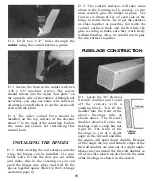


D 16. Assemble the throttle (short) pushrod
by screwing the remaining nylon clevis and
1" long threaded rod into one end of the short
inner pushrod and snapping this assembly
onto the throttle servo horn.
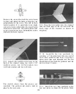
D 18. Slide the two 1/4" plywood landing
gear supports into the fuselage, one on each
side of the aluminum channel. The front of
the supports should be even with the front of
the aluminum channel.
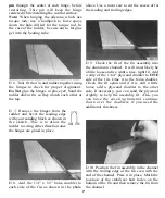
D 17. Attach the plastic fuselage tube to the
channel by sliding it over the c h a n n e l
assembly and pushing the front 8-32 screw
through the middle hole in the bottom of the
tube. Put the aluminum landing gear in place
on the 8-32 screw and secure the whole
assembly with a #8 lock washer and an 8-32
hex nut. Insert the remaining 8-32 screw in
the rear hole from the bottom and secure it
with a # 8 lock washer and an 8-32 hex nut
in the channel. It is a good idea to use some
medium strength thread locking cement on
these bolts.
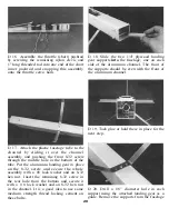
D 19. Tack glue or hold these in place for the
next step.
D 20. Drill a 1/8" diameter hole in each
support using the attached landing gear as a
guide. Remove the supports from the fuselage
20


