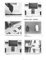
(19) Carefully position the tail control rod into the hole and the groove. Wipe off any
excess epoxy and then insert the hinges into the slots. Wipe off any excess
epoxy from the hinges and check for free operation. Let cure.
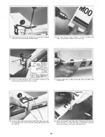
(2) Using PlastiZap again, glue the angled mounting plates, one on each side, on
the two elevator halves as shown.
CONTROL HORN INSTALLATION
(A) Control Horns . . . . . . . . . . . . . . . . . . . . . . . . . . . . . . . . . .3
(B) Back Plates . . . . . . . . . . . . . . . . . . . . . . . . . . . . . . . . . . . .3
(C) Mounting Plates ( R e c t a n g l e d ) . . . . . . . . . . . . . . . . . . . . . . . . . . .2
(D) Mounting Plates ( A n g l e d ) . . . . . . . . . . . . . . . . . . . . . . . . . . . . .4
(E) Brass Tubes . . . . . . . . . . . . . . . . . . . . . . . . . . . . . . . . .6
(F) 2mmx20mm Screws . . . . . . . . . . . . . . . . . . . . . . . . . . . . . . .6
(G) Clevis Retainer Tube . . . . . . . . . . . . . . . . . . . . . . . . . . . . . . .1
(H) Rod Clevis . . . . . . . . . . . . . . . . . . . . . . . . . . . . . . . . . . . .3
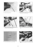
(3) Using the control horns as a guide, center and mark two holes for drilling on all
three mounting plates. The horns will then be mounted — two underneath the
elevator and one on the right side of the rudder (as viewed from the rear).
(1) Glue (use PlastiZap) the rectangular mounting plates to the rudder so that they
are centered, one on each side, over the tail control arm that is "inside" the
rudder.
(4) Drill out 3mm holes for the three horns. Make sure that you drill straight
through to the other side.
21


