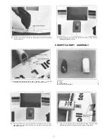
(25) Connect the "Z" bend to the engine throttle arm. It may be necessary to
remove the arm from the engine for easier installation.
(28) Next, at the marked point, make another "Z" bend, cut off the excess and
attach it to the servo arm. For easy adjustments, an easy connect can be used
here. (Dubro #121 E-Z Connectors work well.)
(26) Epoxy the white tube to the tube guide.
(29) Check for proper radio operation of the throttle. Make sure that the carburetor
will move from low to high completely.
ASSEMBLY OF THE TAIL SECTION
(27) From the inside, pull back the throttle control rod so the carburetor is closed.
Now, mark the rod where it crosses the throttle servo horn (in low position).
(A) Horizontal Stabilizer (Stab) . . . . .1
(B) Vertical Fin . . . . . . . . . . . . .1
(C) Rudder . . . . . . . . . . . . . .1
(D) 1/8" Plywood Wedge . . . . . . .1
(E) Stab Root Cover (Plastic) . . . . . .1
(F) Stab. Supports . . . . . . . . . . . .2
(G) Plastic Disc . . . . . . . . . . . . .4
(H) Brass Sleeve . . . . . . . . . . . .2
(I) 2mmx15mm Screw . . . . . . . . .2
(J)2mm Nut . . . . . . . . . . . . . .2
(K) 2mm Washer . . . . . . . . . . . .4
(L) Tail Wheel . . . . . . . . 1
(M) Tail Gear . . . . . . . . . . . . . .1
(N) Tail Control Arm . . . . . . . . . .1
(0) Springs . . . . . . . . . . . . . .2
(P) Brass Arms . . . . . . . . . . . . .2
(Q) Spring Steel Strip (Long) . . . . . .1
(R) 3mmx12mm Self Tapping Screw . .2
(S) 3mmx5mm Screw . . 2
(T) Wheel Collar . . . . . . . 1
(U) Wheel Collar Screw 1
(V) Brass Collars . . . . . . . . 2
.17-


