Hobbico avistar 40 User Manual Download Page 18

FLIGHT CHARACTERISTICS

Pre-Flight Check

1 Clean the dust dirt and oil off of the surface of the airplane

2 Check to make sure all nuts, bolts and screws are securely

fastened

3 Check all control surfaces to see if they are properly attached
4 Check the range of the radio system as the manufacturer recom-

mends

5 Check that all controls move smoothly and in the proper directions
6 Check the level of charge in the transmitter and receiver batteries
7 Check that the area being used is free of obstacles and debris
8 Check the frequencies currently in use at the field and in your area
9 Check the level of the fuel tank to be sure it is full

10 Double check the radio operation

Flight Safety

• If this airplane happens to be your first radio controlled airplane we

strongly suggest that you ask a skilled pilot or instructor to help you
learn how to fly You should also suggest to him to take the maiden
flight to see what problems (if any) that need to be worked out There
will be enough to worry about on your first solo flight without having

to worry about whether or not it is properly set up

• Fly in an open field without any obstructions For example trees

power lines buildings crowds of people etc are abstacles that the
plane may hit and cause damage

• If you are a novice pilot local area clubs have been formed and are

very willing to help you with any questions you may have Many of
the clubs even have club trainer airplanes that they will actually
teach you to fly with This helps prevent disappointing crashes on
your first flights Addresses of local area clubs can be located from
you local area hobby shop and/or by writing to Academy of Model
Aviation 1810 Samuel Morse Drive Reston VA 22090

• Fly the model at a reduced throttle until you get to know the flight

characteristics

• When adjusting the needle valve just prior to flight hold the plane

at a 45° nose up attitude full open throttle and adjust the throttle for
top performance as the manufacturer s instructions suggest

Take-Off

The airplane may be taxied around on a smooth/open section of

pavement without the wing after the engine has been adjusted and the
radio has been properly checked Become familiar with controlling the
plane on the ground with the rudder In the air you will find that most of
the time you will be using a combination of elevator and ailerons to turn
the plane because they are more effective in the air On the ground the
rudder is more effective A transition will need to be made once the
plane leaves the ground That transition from using the rudder on the
ground to using the ailerons once it leaves the ground will take a little
practice One good rule of thumb is to always take off directly into the
wind (if there is any) This will prevent the wind from trying to blow the
model from side to side and will not take as much runway as if you were
trying to take off downwind

Once you feel comfortable with the way it handles on the ground it

comes time for you to concentrate very much on the airplane s move

ments As you are ready for take off simply point the nose into the wind
and slowly advance the throttle up to full throttle At this point the plane

will be going very fast and will be very sensitive to your rudder inputs

Use smooth inputs to correct the plane from wandering off of the
runway Once the plane is at take off speed slowly pull back on the

elevator stick This will cause the plane to leave the ground At this point

notice whether the plane tends to turn climb or dive and make the
necessary opposite control inputs to keep the plane on a gentle climb
in the desired direction

Flight

Once the plane has reached a safe altitude reduce the throttle to

about half power If the airplane is properly set up (i e correct C G
trims all centered engine properly set) the plane should be very stable
without any wandering tendencies If the plane does tend to go one
direction more than another use your trim levers on your transmitter to
correct this Do not look at the transmitter while adjusting trims Then
while the plane is flying straight adjust the elevator trim to correct
abnormal climbing or diving If the trims will not overcome a turn or a
climbing tendency land the model immediately and check for improper
setup

Landing

There is an old saying that states You do not have to take off But

you do have to land Therefore be ready to land at all times during your
flight The engine may not stay running through a complete tank of fuel

for one reason or another It is suggested to time the run time of a
complete tank before flight That way you know approximately what to
expect and when you need to land before the fuel runs out

Set up your landing approach downwind at 100 200 feet up and 500

800 feet away depending on the height of the plane and the strength of
the wind Approach into the wind and slowly reduce the throttle to the
closed position Concentrate on the glide path of the plane taking
notice of whether the plane will reach the beginning of the runway or if
it will overshoot the runway completely With smooth deliberate inputs
use your engine power and your elevator to adjust the glide path so the
plane will touch down smoothly on the beginning of the runway at its
slowest speed It will still seem very fast and will use the complete
runway to slow down

After-Flight Maintenance

• Remove all excess fuel from the fuel tank as this fuel can become

jelly like and cause clogging of fuel lines as well as clogging the

engine s carburetor valves

• Always use after run oil in the engine to prevent corrosion
• Check and double check that the transmitter and receiver switches

are switched to the off positions

• Wipe off the excess oil that will collect on the wing and fuselage Use

a light duty cleanser to help cut through the oil

• Remove fresh fuel from the surface of the plane immediately as

different brands can cause clouding of the surface

• Replace any bent marred or dinged props as they can fly apart at

any time when the engine is running

• Completely check the airplane for damage to the wings landing

gear covering and repair as needed before your next flight

Repair

If damage should occur wipe the broken area clean with a clean rag to
remove all debris use epoxy glue to repair Do not use Cyanoacrylate

adhesive near any foam parts as it will deteriorate the foam

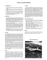
Fully Assembled Avistar

18

Summary of Contents for avistar 40

Page 1: ... ASSEMBLED FOR PERFECT ALIGNMENT AND QUICK ASSEMBLY ALL PRE ASSEMBLED COMPONENTS ARE FACTORY COVERED CLASSIC DESIGN WITH DURABLE BALSA AND PLYWOOD CONSTRUCTION SEMI SYMMETRICAL AIRFOIL GIVES THE AVISTAR 40 PREDICTABLE FLIGHT CHARACTERISTICS ENTIRE CONTENTS COPYRIGHT 1988 HOBBICO INC ...

Page 2: ... kit is one of the finest models of its type and will offer you many hours of enjoyment ADDITIONAL ITEMS Please check the additional items listed below for those materials not furnished but recommended Dubro 163 Wing seat tape 1 Dubro 121 E Z connectors 6 or Goldberg 361 Snap R Keepers 6 Goldberg 482 1 2 foam rubber 1 Goldberg 461 Wing skids 1 Devcon 5250 Silicone rubber 2 oz 1 Dave Brown Products...

Page 3: ...stic disk 1 large 1 small 15 Clunk weight 1 16 Fuel pipe 3 17 M3x18 self tapping screw 1 18 Silicone fuel line 1 19 Center tape 1 20 Servo tray 1 21 Aileron servo tray 1 22 Spinner 1 23 Stabilizer control rods 2 24 Aileron control rods 93 4 2 25 Throttle and nose gear control rods 173 4 2 26 Plastic guide tubes 2 MISC HARDWARE 27 Clevis 4 28 Control horns 2 29 Control horn back plate 2 30 4mm x 10...

Page 4: ...eline along the hinge joint on both sides of the hinge This will prevent epoxy from getting in the hinge joint and ruining the hinge Do not get vaseline on the rest of the hinge If this happens the epoxy will not hold the hinge and the aileron may separate from the wing causing a crash Do this step to all eleven hinges All ailerons are mounted temporary from the factory Remove the ailerons from th...

Page 5: ...dge of the aileron The torque rod is what will transmit motion from the servo to the aileron Install the rudder on the vertical stabilizer and elevator on the horizontal stabilizer using the same procedure used for the aileron Be careful not to leave a gap in the hinge gap With the aileron temporarily installed there should be no gap in the hinge gap If the plane is flown with a hinge gap of more ...

Page 6: ...epoxy to cure Slide the other wing panel onto the wing joiner Slide the two wing halves together Check for proper alignment There should be no gap between the wing halves If there is trim the end of the wing joiner slightly to allow proper fit Do not glue at this time Mark the location on the bottom of the wing where the wing joiner is installed The wing should form a V when assembled as shown The...

Page 7: ... a servo from your radio system Slip the servo into the tray and measure the distance from the bottom of the servo to the bottom of the balsa block Then remove the balsa wood from area B Remove enough balsa wood accomodate the servo previously measured in Step 1 Remove the servo from the servo tray Turn the servo tray upside down balsa blocks up and lay the end of the tray on the line drawn in Ste...

Page 8: ...ction to prevent it getting scraped up The wing dowel holes are also pre drilled They are located in the area indicated in the photo Using a sharp knife remove the covering material at this time There are four holes two on each side of the fuselage Insert the dowels so that they protrude equal distance on each side of the fuselage Epoxy part of the dowel protruding from the sides of the fuselage T...

Page 9: ...ese steps so that you are totally familier with its sequence Using wing saddle tape apply a strip to the wing saddle area as shown Mark on the stabilizer where the fuselage and the stabilizer touch Do this on the top and the bottom of the stabilizer Remove the covering in between the two lines This will allow a more secure glue joint when the stabilizer is epoxyed later Do not cut the balsa wood u...

Page 10: ...to see if you have equal distance from the center of the tail to the outside edge of the stab Now using the string explained in the stabilizer preparation section adjust the stabilizer so it is 90 to the center line of the fuselage Mix a small batch of epoxy and apply it to the area inside the fuselage on the surface of the exposed wood Apply an even coat to the vertical stabilizer base where you ...

Page 11: ...t Insert the white plastic tube through the holes so that the end of the tube is even with the bottom of the fuselage Epoxy the tube to the fuel tank mounts and the bottom of the fuselage Slide the nose gear shaft through the nose gear mount Secure the gear in place with a 4mm x 10mm wheel collar and m3x4 screw Slide the 17 3 4 control rod into the white tube in the bottom of the fuselage Connect ...

Page 12: ...otruding out of the front of the firewall Install the control rod on the throttle control horn following the manufacturer s instructions Next slide the control rod into the white plastic tube installed in the firewall Secure the engine to the engine mount Slide a 4mm washer onto a 3mm x 20mm screw Insert the screw through the engine mounting holes Apply zap lock to the threads of the screw where t...

Page 13: ...his side will prevent fuel from damaging the switch Install the muffler following the manufacturers instructions Connect the pros sure line to the muffler pressure tap Test fit your servos into the servo tray Trim the tray as necessary to tit If mini sized or over sized servos are being used it may be necessary to make an additional servo tray We recommend using standard size servos Arrange them a...

Page 14: ...fuselage This may take some time Install the nylon clevis onto the threaded end of the push rod Mount the rudder control horn so that it is on the center line of the hinge joint and pointing toward the push rod as shown Mark the location of the two mounting holes and drill a hole on the marks Insert the m2x2 screws through the horn and into the control horn back plate Attach the clevis to the cont...

Page 15: ... arm on may need to be removed so that the arm can be removed and adjusted Make a 90 bend at the mark on the push rods Cut the excess wire as shown and install the Snap R Keepers to the rod and servo arms following the manufacturers instructions If using E Z connectors install them on the servo arms and attach the rods following the manufacturer s instructions Set the rudder and elevator so that t...

Page 16: ... prevent ma or damage Four rubber bands are needed per side CENTER OF GRAVITY The center of gravity is a very important aspect of setting up the airplane properly It will control a large part of what type of flying characteristics your plane will have it it is nose heavy C G s too far forward the airplane will try to dive and the elevator will be sluggish to respond to your control inputs If the p...

Page 17: ...se a few times Notice the fuel line If any fuel is being sucked into the carburetor turn the prop a few more times If no fuel is reaching the carburetor recheck the fuel line plumbing 6 Reduce the throttle to 1 4 or 1 2 throttle for starting 7 Using a starting stick chicken stick and holding the fuselage firmly quickly flip the prop in the counter clockwise direction Do not attach the glow plug cl...

Page 18: ... into the wind and slowly advance the throttle up to full throttle At this point the plane will be going very fast and will be very sensitive to your rudder inputs Use smooth inputs to correct the plane from wandering off of the runway Once the plane is at take off speed slowly pull back on the elevator stick This will cause the plane to leave the ground At this point notice whether the plane tend...

Page 19: ...ly steer the Avistar left or right as necessary to obtain a straight take off 7 After the plane has gained speed gently pull back on the elevator stick Do not allow the plane to climb too steeply 8 Keep the wings level and reduce the throttle some to obtain a gentle climb 9 To turn gently move the aileron stick to the side and pull back on the elevator If too much aileron is used the plane will ba...

Page 20: ......

Reviews: