


ENGINE INSTALLATION
Install the back plate of the spinner then install the prop so that when the prop
is at 2 o'clock there is resistance from the compression of the engine Tighten the
prop nut securely and install the spinner using the two screws that came with the
spinner
If using the Snap R Keeper make a 90° bend 5/16 from the end of the 17 3/
4 control rod as shown If using the E-Z connector, install the connector on the
throttle control horn following the manufacturer's instructions.
Locate the pre drilled 1/8" hole in the firewall Before installing the white plastic
tube rough it up with 240 grit sandpaper This will help the epoxy to hold better
Install the white plastic tube into the hole Epoxy the tube to the firewall leaving
approximately 1/2 of the tube protruding out of the front of the firewall
Install the control rod on the throttle control horn following the manufacturer's
instructions Next slide the control rod into the white plastic tube installed in the
firewall Secure the engine to the engine mount Slide a 4mm washer onto a 3mm
x 20mm screw Insert the screw through the engine mounting holes Apply zap-
lock to the threads of the screw where they protrude from the engine mount
Install a 4mm washer then a 3mm nut Tighten the nut securely The zap lock will
prevent the nut from vibrating loose
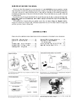
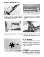
ASSEMBLY OF FUEL TANK
Set the engine on the engine mount so that the propeller clears the front of the
fuselage and the center line of the engine is in line with the center line of the
fuselage Mark the engine mounting holes Remove the engine and drill four
1/8" holes on the marks
Assemble the fuel tank as shown Apply a bead of silicone sealant around the
fuel tank cap as shown when installing it into the fuselage
12
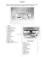
Summary of Contents for avistar 40
Page 20: ......


