


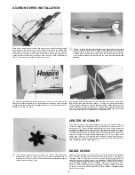


CONTROL HORN INSTALLATION
Plug the servos and switch into the receiver and the receiver battery into the
switch Then wrap the receiver and the receiver battery in natural foam Use
rubber bands to loosely hold the foam in place This foam packing protects the
radio components from damaging engine vibrations Place the battery toward
the front of the compartment
When installing control horns the center line of the control horn holes must be the
same as the center line of the hinge joint If not the control surface will move
farther one way than the other
PUSH ROD INSTALLATION
Insert the threaded end of the rudder pushrod into the fuselage working it around
until the end of the push rod is extending through the exit hole on the top of the
fuselage This may take some time Install the nylon clevis onto the threaded end
of the push rod
Mount the rudder control horn so that it is on the center line of the hinge joint and
pointing toward the push rod as shown Mark the location of the two mounting
holes and drill a hole on the marks Insert the m2x2 screws through the horn and
into the control horn back plate Attach the clevis to the control horn
Insert the threaded end of the elevator pushrod into the fuselage working it
around until the end of the rod is extending through the exit hole on the left lower
side of the fuselage This may take some time Install the nylon clevis onto the
threaded end of the push rod
Mount the elevator control horn on the elevator so it is on the elevator hinge joint
center line and pointing toward the elevator pushrod Using the same procedure
as before install the m2x12 screws and control horn back plate Attach the clevis
to the control horn
14
Summary of Contents for avistar 40
Page 20: ......


