Hobbico avistar 40 User Manual Download Page 16

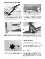
AILERON SERVO INSTALLATION

Route the servo wire through the side of the tray as shown Using the screws supplied

with your radio mount the servo into the tray Install the clevises on the threaded ends
of the aileron control rods Connect the control rods to the aileron horns Center the
aileron servo arm and measure the length of rod needed Use the same procedure to
connect the aileron control rods to the servo arms as used in control rod adjustment

Step 5 Uneven aileron centering will cause severe turns

Drill a 1 /16 hole in the side of the fuselage and the upper portion of the vertical
stabilizer Install the strain relief close to the receiver Route the receiver antenna

through the holes as shown This configuration should allow for the best radio

reception Move the strain relief up to the hole in the fuselage Leave some slack
in the antenna between the receiver and the strain relief Do not cut the

antenna.

Turn both the transmitter and receiver switches on Center the trim levers on the
transmitter Rotate the adjusters in the proper direction to center the control surfaces
(clockwise-shortens the length) The rudder should have 1" of throw to each side The
elevator 1/2" up and 1/2" down

At this time be certain that the aileron servo is connected to the receiver otherwise the
wing will need to be removed later to connect it The wing is mounted to the fuselage
by using (8) #64 rubber bands Wrap the bands around the wooden dowels as shown
above This design is to allow for those not so perfect landings that come with learning
how to fly The bands are designed to pop off during hard landings and thus help
prevent ma)or damage Four rubber bands are needed per side

CENTER OF GRAVITY

The center of gravity is a very important aspect of setting up the airplane properly It
will control a large part of what type of flying characteristics your plane will have it it
is nose heavy (C G s too far forward) the airplane will try to dive and the elevator will
be sluggish to respond to your control inputs If the plane is tail heavy (C G s too

far back) the airplane will be very sensitive to the elevator and possibly uncontrollable

The center of gravity should be checked with the fuel tank empty in the plane to be
accurate The range in which the airplane should balance is 3" to 3 1/4" back from the
leading edge of the wing With standard radio equipment the plane should balance

within this range It it does not balance within this range, feel free to add weight to the

nose or tail as you need to obtain proper C G

RADIO CHECK

If the receiver antenna should get cuaght the receiver could possibly be

damaged By putting a strain relief on the antenna the damage may be
prevented Cut an arm off of a servo arm as shown above and thread the receiver
antenna through the three holes

Always check the operation of your radio before you fly to see that the control surfaces

move in the proper directions and that they move the proper amount If the direction

of rotation needs to be reversed to correct for reversed controls simply change the
side of the servo arm to which the push rod is attached To INCREASE the amount
of movement that the surface will have move the CLEVIS CLOSER to the surface or

move the (SNAP R KEEPER OR E Z CONNECTOR) away from the center of the

servo arm To DECREASE the amount of movement, move the CLEVIS AWAY from
the surface or move the (SPAN'R- KEEPER OR E-Z CONNECTOR) closer to the
center of the servo arm

16

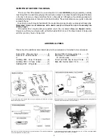
Summary of Contents for avistar 40

Page 1: ... ASSEMBLED FOR PERFECT ALIGNMENT AND QUICK ASSEMBLY ALL PRE ASSEMBLED COMPONENTS ARE FACTORY COVERED CLASSIC DESIGN WITH DURABLE BALSA AND PLYWOOD CONSTRUCTION SEMI SYMMETRICAL AIRFOIL GIVES THE AVISTAR 40 PREDICTABLE FLIGHT CHARACTERISTICS ENTIRE CONTENTS COPYRIGHT 1988 HOBBICO INC ...

Page 2: ... kit is one of the finest models of its type and will offer you many hours of enjoyment ADDITIONAL ITEMS Please check the additional items listed below for those materials not furnished but recommended Dubro 163 Wing seat tape 1 Dubro 121 E Z connectors 6 or Goldberg 361 Snap R Keepers 6 Goldberg 482 1 2 foam rubber 1 Goldberg 461 Wing skids 1 Devcon 5250 Silicone rubber 2 oz 1 Dave Brown Products...

Page 3: ...stic disk 1 large 1 small 15 Clunk weight 1 16 Fuel pipe 3 17 M3x18 self tapping screw 1 18 Silicone fuel line 1 19 Center tape 1 20 Servo tray 1 21 Aileron servo tray 1 22 Spinner 1 23 Stabilizer control rods 2 24 Aileron control rods 93 4 2 25 Throttle and nose gear control rods 173 4 2 26 Plastic guide tubes 2 MISC HARDWARE 27 Clevis 4 28 Control horns 2 29 Control horn back plate 2 30 4mm x 10...

Page 4: ...eline along the hinge joint on both sides of the hinge This will prevent epoxy from getting in the hinge joint and ruining the hinge Do not get vaseline on the rest of the hinge If this happens the epoxy will not hold the hinge and the aileron may separate from the wing causing a crash Do this step to all eleven hinges All ailerons are mounted temporary from the factory Remove the ailerons from th...

Page 5: ...dge of the aileron The torque rod is what will transmit motion from the servo to the aileron Install the rudder on the vertical stabilizer and elevator on the horizontal stabilizer using the same procedure used for the aileron Be careful not to leave a gap in the hinge gap With the aileron temporarily installed there should be no gap in the hinge gap If the plane is flown with a hinge gap of more ...

Page 6: ...epoxy to cure Slide the other wing panel onto the wing joiner Slide the two wing halves together Check for proper alignment There should be no gap between the wing halves If there is trim the end of the wing joiner slightly to allow proper fit Do not glue at this time Mark the location on the bottom of the wing where the wing joiner is installed The wing should form a V when assembled as shown The...

Page 7: ... a servo from your radio system Slip the servo into the tray and measure the distance from the bottom of the servo to the bottom of the balsa block Then remove the balsa wood from area B Remove enough balsa wood accomodate the servo previously measured in Step 1 Remove the servo from the servo tray Turn the servo tray upside down balsa blocks up and lay the end of the tray on the line drawn in Ste...

Page 8: ...ction to prevent it getting scraped up The wing dowel holes are also pre drilled They are located in the area indicated in the photo Using a sharp knife remove the covering material at this time There are four holes two on each side of the fuselage Insert the dowels so that they protrude equal distance on each side of the fuselage Epoxy part of the dowel protruding from the sides of the fuselage T...

Page 9: ...ese steps so that you are totally familier with its sequence Using wing saddle tape apply a strip to the wing saddle area as shown Mark on the stabilizer where the fuselage and the stabilizer touch Do this on the top and the bottom of the stabilizer Remove the covering in between the two lines This will allow a more secure glue joint when the stabilizer is epoxyed later Do not cut the balsa wood u...

Page 10: ...to see if you have equal distance from the center of the tail to the outside edge of the stab Now using the string explained in the stabilizer preparation section adjust the stabilizer so it is 90 to the center line of the fuselage Mix a small batch of epoxy and apply it to the area inside the fuselage on the surface of the exposed wood Apply an even coat to the vertical stabilizer base where you ...

Page 11: ...t Insert the white plastic tube through the holes so that the end of the tube is even with the bottom of the fuselage Epoxy the tube to the fuel tank mounts and the bottom of the fuselage Slide the nose gear shaft through the nose gear mount Secure the gear in place with a 4mm x 10mm wheel collar and m3x4 screw Slide the 17 3 4 control rod into the white tube in the bottom of the fuselage Connect ...

Page 12: ...otruding out of the front of the firewall Install the control rod on the throttle control horn following the manufacturer s instructions Next slide the control rod into the white plastic tube installed in the firewall Secure the engine to the engine mount Slide a 4mm washer onto a 3mm x 20mm screw Insert the screw through the engine mounting holes Apply zap lock to the threads of the screw where t...

Page 13: ...his side will prevent fuel from damaging the switch Install the muffler following the manufacturers instructions Connect the pros sure line to the muffler pressure tap Test fit your servos into the servo tray Trim the tray as necessary to tit If mini sized or over sized servos are being used it may be necessary to make an additional servo tray We recommend using standard size servos Arrange them a...

Page 14: ...fuselage This may take some time Install the nylon clevis onto the threaded end of the push rod Mount the rudder control horn so that it is on the center line of the hinge joint and pointing toward the push rod as shown Mark the location of the two mounting holes and drill a hole on the marks Insert the m2x2 screws through the horn and into the control horn back plate Attach the clevis to the cont...

Page 15: ... arm on may need to be removed so that the arm can be removed and adjusted Make a 90 bend at the mark on the push rods Cut the excess wire as shown and install the Snap R Keepers to the rod and servo arms following the manufacturers instructions If using E Z connectors install them on the servo arms and attach the rods following the manufacturer s instructions Set the rudder and elevator so that t...

Page 16: ... prevent ma or damage Four rubber bands are needed per side CENTER OF GRAVITY The center of gravity is a very important aspect of setting up the airplane properly It will control a large part of what type of flying characteristics your plane will have it it is nose heavy C G s too far forward the airplane will try to dive and the elevator will be sluggish to respond to your control inputs If the p...

Page 17: ...se a few times Notice the fuel line If any fuel is being sucked into the carburetor turn the prop a few more times If no fuel is reaching the carburetor recheck the fuel line plumbing 6 Reduce the throttle to 1 4 or 1 2 throttle for starting 7 Using a starting stick chicken stick and holding the fuselage firmly quickly flip the prop in the counter clockwise direction Do not attach the glow plug cl...

Page 18: ... into the wind and slowly advance the throttle up to full throttle At this point the plane will be going very fast and will be very sensitive to your rudder inputs Use smooth inputs to correct the plane from wandering off of the runway Once the plane is at take off speed slowly pull back on the elevator stick This will cause the plane to leave the ground At this point notice whether the plane tend...

Page 19: ...ly steer the Avistar left or right as necessary to obtain a straight take off 7 After the plane has gained speed gently pull back on the elevator stick Do not allow the plane to climb too steeply 8 Keep the wings level and reduce the throttle some to obtain a gentle climb 9 To turn gently move the aileron stick to the side and pull back on the elevator If too much aileron is used the plane will ba...

Page 20: ......

Reviews: