background image

17

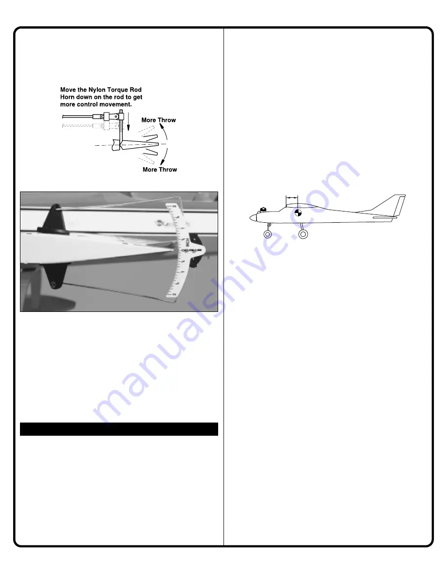
If you need more control movement, you can move the nylon
horn closer to the control surface or you can move the rod at
the servo away from the center of the servo horn. If you have
too much movement, reverse the process. 

One leading cause of crashes is flying an airplane with its
control throws set differently from those recommended in the
instructions. The Great Planes AccuThrow

lets you quickly

and easily measure actual throws first, so you can make
necessary corrections before you fly. Large, no-slip rubber feet
provide a firm grip on covered surfaces without denting or
marring the finish. Spring tension holds AccuThrow’s plastic
ruler steady by each control surface. Curved to match control
motions, the ruler provides exact readings in both standard or
metric measurements. 

GPMR2405.

CHECK THE LATERAL BALANCE

Now that you have the model completed, this is a good time to
balance the airplane laterally (side-to-side). Here is how to 
do it:

1. Attach the wing to the fuselage.

2. With the airplane sitting level, lift the model by the engine

propeller shaft and the bottom of the fuselage at the tail (this
may require two people). Do this several times.

3. If one wing always drops when you lift the model, it

means that side is heavy. Balance the airplane by attaching
weight to the lighter wing tip. 

Note:

An airplane that has been

laterally balanced will track better in loops and other
maneuvers. Balancing weight is available from your local
hobby dealer.

CHECK THE FORE-AFT BALANCE (CENTER OF GRAVITY)

Note:

This section is 

VERY

important and must 

NOT 

be

omitted! A model that is not properly balanced will be unstable
and possibly unflyable.

1. Accurately mark the balance point on the bottom of the

wing on both sides of the fuselage. The balance point is 
located 3-3/8” (85mm) back from the leading edge. This is the
balance point at which your model should balance for your first
flights. Later, you may wish to experiment by shifting the
balance up to 1/4" (6mm) forward or back to change the flying
characteristics. Moving the balance forward may improve the
smoothness and arrow-like tracking, but it may then require
more speed for takeoff and make it more difficult to slow down
for landing. Moving the balance aft makes the model more
agile with a lighter and snappier “feel”. In any case, please
start at the location we recommend and do not at any time
balance your model outside the recommended range.

2. With the wing attached to the fuselage, all parts of the

model installed (ready to fly), and an 

empty 

fuel tank, position

your fingertips at the marked balance point.

3. Lift the model. If the tail drops when you lift, the model is

“tail heavy” and you must add weight* to the nose. If the nose
drops, it is “nose heavy” and you must add weight* to the tail
to balance.

Note:

Nose weight may be easily installed by using a Heavy

Spinner Hub or gluing lead weights to the firewall. Tail weight
may be added by using Great Planes (GPMQ4485) “stick-on”
lead weights.

*If possible, first attempt to balance the model by changing the
position of the receiver battery and receiver. If you are unable
to obtain good balance by doing so, then it will be necessary
to add lead weights to the nose or tail to achieve the proper
balance point.

CG

3-3/8"

(85mm)

BALANCE YOUR MODEL

IMPORTANT!

Summary of Contents for AirVista

Page 1: ...ft The video Getting to the Flying Field makes mastering Radio Control even easier watch it before getting started Builds with 2 tools in 1 evening We guarantee your success Assembly Instructions Copy...

Page 2: ...on form This form will verify that all terms and conditions of the flight guarantee have been followed and signatures from you and your AMA club qualified instructor have been obtained This guarantee...

Page 3: ...ly ready to solo Your local hobby shop has information about flying clubs in you area whose membership includes qualified instructors You can also contact the national Academy of Model Aeronautics AMA...

Page 4: ...x 10mm Sheet Metal Screws 4 4 x 5 8 Sheet Metal Screws 2 4 40 Lock Nuts 1 48 Drill Bit 2 4 40 x 1 8 Phillips Head Screw 6 4 Washers 1 Fuel Tank Assembly 2 Flat Landing Gear Straps 4 4 x 20mm Screws 4...

Page 5: ...tem select four arms that look like an X or Star and snap off the sides with your pliers A diagonal cutter works well also STEP 3 Choose the Control Arms A A Connect your radio system and turn it on B...

Page 6: ...wire STEP 7 Install the Aileron Servo STEP 6 Install the Receiver and Battery A A Position the servos where shown Note the orientation B B Using the screws that came with the radio system attach the s...

Page 7: ...o the Ailerons Rudder and Elevator Use the L shaped plywood gauge to set the height of the horns on each torque rod STEP 1 Install the FOUR Torque Rod Horns Steel Rod Wing Panel The servo wire should...

Page 8: ...e Use the two 4 40 lock nuts along with washers to hold the tail in place STEP 2 Install the Fin STEP 3 Install the Wing Dowels Fuselage Bottom 4 40 Lock Nut 2 4 Washer 2 Actual Size 2 5 x 10mm Screw...

Page 9: ...d on the firewall STEP 2 Install the Fuel Tank Insert the two longest Pushrods into the tubes from inside the fuselage The longer of the two pushrods goes here If the pushrod guides are not pre instal...

Page 10: ...ert the pushrods from the bottom of the servo arms for easier installation remove the arms from the servos B B Install the nylon pushrod retainers STEP 5 Hook Up the Servos Nylon Pushrod Retainer 2 A...

Page 11: ...l provided B B Make sure the servos do not move C C Screw the clevises on so that the control surfaces are centered Attach the clevises to the horns D D Slide the retainers over the clevises STEP 6 At...

Page 12: ...connector STEP 1 Install the Steering Hardware Landing Gear Installation Part Part A A Insert the two main landing gear wires into the slots on the bottom of the fuselage B B Secure the landing gear...

Page 13: ...ion Part Part Four Four STEP 1 Install the Engine C C Attach the clevis to the throttle arm and slide the retainer in place 4 x 20mm Screw 4 4 x 20mm Screws Tip If installing an O S 40 LA engine insta...

Page 14: ...may need to trim the cowl to provide access to the needle valve B B At the holes in the cowl use the four 2 5 x 10mm screws to attach the cowl in place If there is a lot of extra tubing you may cut o...

Page 15: ...ount of tension on the antenna wire A A Insert the T Pin into the top of the fin just in front of the plastic tip Nylon Strap 1 Longer Slot Strain Relief 4 4 2 2 I Im mp po or rt ta an nt t Plug the a...

Page 16: ...hen the carburetor barrel will stop fully open at the same time the throttle stick reaches full With the throttle set up properly you should be able to run the engine with the trim lever set midway to...

Page 17: ...Y important and must NOT be omitted A model that is not properly balanced will be unstable and possibly unflyable 1 Accurately mark the balance point on the bottom of the wing on both sides of the fus...

Page 18: ...ties CHARGE THE BATTERIES Follow the battery charging procedures in your radio instruction manual You should always charge your transmitter and receiver batteries the night before you go flying and at...

Page 19: ...d condition so fuel will not leak onto a hot engine To stop the engine cut off the fuel supply by closing off the fuel line or follow the engine manufacturer s recommendations Do not use hands fingers...

Page 20: ...R C pilots have taught themselves to fly we strongly recommend that you find an instructor to help get you started Although trainer airplanes offer the greatest opportunity of success for the self tau...

Page 21: ...n torque rod excessive flexing of aileron caused by using too soft balsa aileron excessive play or backlash in servo gears and insecure servo mounting LANDING When it s time to land fly a normal landi...

Page 22: ...e the intake line is always in fuel Dead Stick A term used to describe unpowered flight glide when the engine quits running Differential Throw Ailerons that are set up to deflect more in the upward di...

Page 23: ...This type of glow plug has a bar across the tip to help prevent raw fuel from being splashed onto the glow element Too much raw fuel will cool the plug and prevent it from igniting the fuel air mixtur...

Page 24: ...designed specifically to count light impulses through a turning propeller and read out the engine RPM Tip Stall The outboard end of one wing the tip stops developing lift causing the plane to roll sud...

Reviews: