HV100 Series High Performance Current Vector Inverter
96
07.38
Y2 delay time of disconnect
0.0
~
100.0s
0.0
07.39
R1 delay time of disconnect
0.0
~
100.0s
0.0
07.40
R2 delay time of disconnect
0.0
~
100.0s
0.0
008 group -PID control parameters
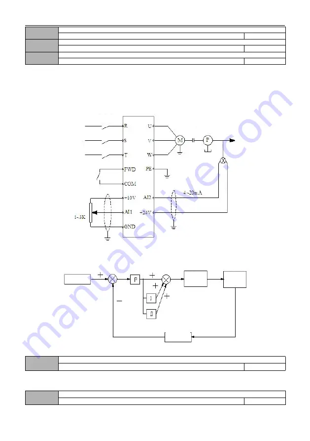
By setting this parameter group, a complete control system of analog feedback can be formed.
Control system of analog feedback: the setting value is input with AI1, and the physical value of the controlled object is
converted into 4 ~ 20mA current, which is input through AI2 of the inverter. The current goes through the built-in PI
regulator, so that forms an analog closed-loop control system, as shown in the below figure:
Figure F8-1 Schematic diagram of analog feedback control system
PID regulation functions are as follows:
Fig. F8-2 PID regulation schematic diagram
08.00
PID operation mode
0
~
1
0
0: Automatic
1: manually input through the defined multi-function terminal
08.01
PID setting channel selection
0
~
6
0
Power
supply
Breaker
FWD/Stop
command
Setting value
Drive part
Sensor
Setting value
Feedback
regulation
Feedback
quantity
Drive part
Controlled
object


