


HV100 Series High Performance Current Vector Inverter
128
Chapter IX Fault Diagnosis and Countermeasures
9.1 Fault Alarm and Countermeasures
In case of abnormality during operation, the inverter immediately blocks the PWM output and enters the fault protection
state. At the same time, the current fault information is indicated by the flashing fault code on the keyboard. At the same
time, the fault indicator ALM lights up. At this time, it is necessary to check the cause of the fault and the corresponding
treatment method according to the method suggested in this section. If the problem still cannot be solved, please contact
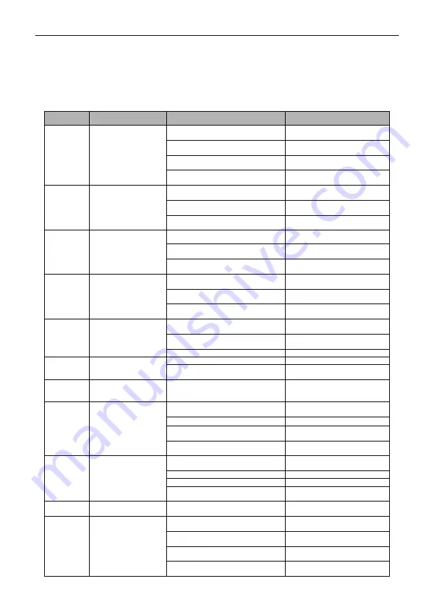
our company directly. Please refer to Table 9-1 Fault Diagnosis and Elimination for corresponding solutions.
Fault code
Name
Possible reason of fault
Fault countermeasures
E-01
Overcurrent during
acceleration
Acceleration time is too short
(including tuning process)
Extended the acceleration time
Restart the rotating motor
Set to start after DC braking or
speed tracking start
Low inverter power
Choose a inverter with high
power level
Improper setting of V/F curve or
torque boost
Adjust V/F curve or torque lift
E-02
Overcurrent during
deceleration
Deceleration time is too short
(including tuning process)
Extended deceleration time
Low inverter power
Choose a inverter with high
power level
Excessive load inertia
External braking resistor or
braking unit
E-03
Overcurrent in
constant speed
Low grid voltage
Check the input power supply
The load is mutated or abnormal
Check the load or reduce the
load mutation
Low inverter power
Choose a inverter with high
power level
E-04
Overvoltage during
acceleration
Abnormal input voltage (including
tuning process)
Check the input power supply
Restart the rotating motor
Set to start after DC braking or
speed tracking start
Special potential energy load
External braking resistor or
braking unit
E-05
Overvoltage during
deceleration
Deceleration time is too short
(including tuning process)
Extended deceleration time
Excessive load inertia
External braking resistor or
braking unit
Input voltage abnormal
Check the input power supply
E-06
Overvoltage in
constant speed
Input voltage abnormal
Check the input power supply
Special potential energy load
External braking resistor or
braking unit
E-07
DC Bus undervoltage
Input voltage is abnormal or
contactor (relay) is not pulled in
Check the power supply
voltage or ask the
manufacturer for service
E-08
Motor overload
Improper setting of V/F curve or
torque boost
Adjust V/F curve or torque lift
Grid voltage is too low
Check the grid voltage
The motor is locked or the load
mutation is too large
Check the load
Motor overload protection factor is
not set correctly
correctly set Motor overload
protection coefficient
E-09
Inverter overload
Improper setting of V/F curve or
torque boost
Adjust V/F curve or torque lift
Grid voltage is too low
Check the grid voltage
Acceleration time is too short
Extended the acceleration time
The motor is overloaded
Choose a inverter with higher
power
E-10
Inverter drop load
Output current is less than load drop
detection value
Check the load
E-11
Power module failure
Inverter output short circuit or
grounding
Check the motor wiring
Instantaneous overcurrent of
inverter
See overcurrent
countermeasures
Blocked air duct or damaged fan
Clear the air duct or replace the
fan
Abnormal control keypador serious
interference
Seek services from
manufacturers


