


28
SW4
S
P
D
1
S
P
D
0
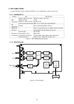
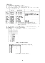
2.3.3 Board Settings
The following diagram shows HPC104-MCAT110M settings to be configured. Configure the access space,
bus width, address, interrupt selection, communication speed, and emergency stop circuit settings.
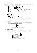
Figure 2.3-2 HPC104-MCAT110M connector and switch positions
(1)
Interrupt selection setting
Figure 2.3-3 Interruption jumpers
(2)
Communication speed setting
If communication errors occur frequently due to the installation environment etc, use a lower
communication speed. Make sure that each slave to connect is also configured with the same
communication speed. Normally, this setting does not need to be changed.
Figure 2.3-4 Communication speed switch
The default of
jumper
connection is
between 9 and 10
(No interruption)
When interrupting the CPU,
any from IRQ05 to 12
should be the opposing jumper.
(Make sure each board is
jumper-wired to a unique interruption
level)
10
1
6
5
P1
IRQ12
IRQ11
IRQ07
IRQ06
IRQ05
Emergency stop
voltage setting switch
switch
Emergency stop
input enabled
(Short: Disabled)
Communication
speed setting
Bus width of
access space
and address
setting
Interrupt selection
setting
2.5Mbps
5Mbps
10Mbps
20Mbps
SPD0
SPD1
ON
OFF
ON
ON
ON
OFF
OFF
OFF
Summary of Contents for motionCAT HCPCI-MNT720M
Page 3: ......
Page 12: ...1 Warnings and Precautions...
Page 20: ...9 1 motionCAT Installation...
Page 109: ...98 4 Installation Guide...
Page 118: ...107 5 Device Driver Installation...
Page 122: ...111 6 Trial Operation...
Page 145: ...134 7 Accessories...
Page 147: ...136 8 Glossary...
Page 161: ...150 9 Connections to Drivers Supplied by Manufacturers...


