


104
Fuse
Fuse
Fuse
+24V
power
supply
+
-
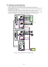
Fuses inserted into the lines.
Wire with enough diameter to carry the
current required by the number of
slaves.
Terminal block
AWG22 - 18 (0.3 to 0.9mm
2
stranded wire)
(3)
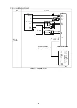
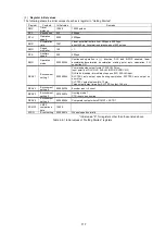
Using separate power supplies for modules ... Power feeding method suited for DIO modules
This method is effective under the following conditions:
When preparing another power supply based on the current capacity (DIO slave etc.);
When the output load power of this module including its GND system must be completely isolated from
other modules.
In the figure below, power supply (2) and power supply (1) are completely independent. The power supply
terminal of the module provides power to the output side of the photocoupler.
Since power supply (1) is shared by the communication module and each of the modules, the GND system
is common among them.
Figure 4.2-3 Using separate power supplies for modules
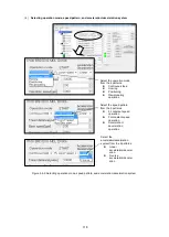
(4)
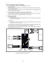
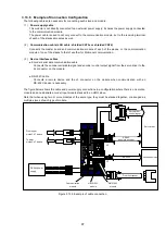
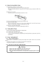
Power supply system connections with slaves
⚫
Use a terminal block to install power supply wiring line by line.
⚫
Use wires - between the power supply and the terminal block - with enough diameter to carry the
current required by the number of slaves.
Figure 4.2-4 Power supply system connections with slaves
+
-
-
+24V
power
supply
+
-
-
+24V
power
supply
(1)
(2)
Summary of Contents for motionCAT HCPCI-MNT720M
Page 3: ......
Page 12: ...1 Warnings and Precautions...
Page 20: ...9 1 motionCAT Installation...
Page 109: ...98 4 Installation Guide...
Page 118: ...107 5 Device Driver Installation...
Page 122: ...111 6 Trial Operation...
Page 145: ...134 7 Accessories...
Page 147: ...136 8 Glossary...
Page 161: ...150 9 Connections to Drivers Supplied by Manufacturers...


