background image

OEM MANUAL:K6602924

5  COMMAND DESCRIPTIONS

Revision: 1 / Date: 2003.03.06

Page: 91  / 273

The parameter list length field designates the length in bytes of the log parameter

list (log pages) to be transferred from the initiator to the drive in the phase of DATA

OUT.  A parameter list of zero indicates no log pages will be sent out from the

initiator.  This condition will not be treated as an error.

If page codes or parameter codes within the parameter list sent out by the initiator

are reserved or not implemented by the drive, the drive will terminate the LOG

SELECT command with CHECK CONDITION status.  The sense key will be set to

ILLEGAL REQUEST and the additional sense code will be INVALID FIELD IN

PARAMETER LIST.

If a parameter list length results in the truncation of any log parameter the drive will

terminate the command with CHECK CONDITION status.  The sense key will be

ILLEGAL REQUEST and the sense code will be INVALID FIELD IN PARAMETER

LIST.

The log pages should be sent in ascending order by page code value if multiple pages

are sent by the initiator.  The log parameters also have to be sent in ascending order

by parameter code value if multiple log parameters within a page are sent.  The

drive will return CHECK CONDITION status if the initiator sends or parameters

out of order.  In this case, the sense key will be ILLEGAL REQUEST and the sense

code will be INVALID FIELD IN PARAMETER LIST.

Initiators shall issue LOG SENSE commands to determine supported pages and page

lengths before issuing LOG SELECT commands.

The drive supports only one set of log parameters for all the initiators. Therefore, if

one initiator modifies a log parameter that will affect other initiators, the drive will

generate an UNIT ATTENTION condition for all initiators except the one that issues

the LOG SELECT command to change it.  This UNIT ATTENTION condition is

returned with an additional sense code of LOG PARAMETERS CHANGED.

[ Log Pages ]

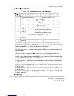
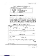
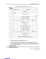
Following a LOG SELECT command, zero or more log pages can be sent out by the

initiator in a DATA OUT phase.  Only one log page will be returned by the drive

in a DATA IN phase after received a LOG SENSE command.  A log page starts

with four-byte page header followed by zero or more variable-length log

parameters for that page.  The log page format is shown as Table 5.19.

LOG SELECT:(4Ch)

Summary of Contents for Ultrastar 15K73

Page 1: ...2924 Revision 1 Date 2003 03 06 Page 1 273 HITACHI3 5 INCH MAGNETIC DISK DRIVE Reference Manual For Ultrastar 15K73 SCSI Interface Specification Document Number K6602924 SCSI 2 3 SPECIFICATIONS Hitachi Ltd Tokyo Japan ...

Page 2: ...istency Hitachi makes no representations or warranties with respect to the contents hereof and specifically disclaims any implied warranties or merchantability or fitness for any purpose Further Hitachi reserves the right to revise this publication and to make changes from time to time in the content hereof without obligation to notify any person of such revisions or changes All Right Reserved Cop...

Page 3: ... DWN Shikama 1 Change of model name CH CHK Shikama 15 Change of revision number of related CH APPD Takayasu document 15 Change of Product Specification document name CH 74 Delete the description about the defect descriptions in the ascending order of address in case of block format DL 210 Change the description about the defect descriptions in the ascending order of address in case of block format...

Page 4: ...OEM MANUAL K6602924 Revision 1 Date 2003 03 06 Page 4 273 REV Date Signature Page Description Remarks REVISION ...

Page 5: ...OEM MANUAL K6602924 Revision 1 Date 2003 03 06 Page 5 273 REV Date Signature Page Description Remarks REVISION ...

Page 6: ...OEM MANUAL K6602924 Revision 1 Date 2003 03 06 Page 6 273 REV Date Signature Page Description Remarks REVISION ...

Page 7: ...MANDS 28 3 SCSI BUS 31 3 1 SCSI BUS FUNCTIONS 31 3 1 1 COMMAND RECEPTION 31 3 1 2 COMMAND QUEUING 31 3 1 3 DISCONNECT RECONNECT 32 3 1 4 UNIT ATTENTION CONDITION 33 3 1 5 ATTENTION CONDITION 33 3 1 6 RESET CONDITION 33 3 2 MESSAGES 34 3 2 1 MESSAGE PROTOCOL 34 3 2 2 MESSAGES 35 3 2 3 EXTENDED MESSAGE 41 3 3 STATUS 49 3 4 SCSI BUS ERROR CONDITIONS 51 3 4 1 TARGET MODE ERROR CONDITIONS 51 3 4 2 INIT...

Page 8: ... 194 5 11 READ 08H 199 5 12 READ EXTENDED 28H 200 5 13 READ BUFFER 3CH 202 5 14 READ CAPACITY 25H 206 5 15 READ DEFECT DATA 37H 208 5 16 READ DEFECT DATA 12 B7H 211 5 17 READ LONG 3EH 213 5 18 REASSIGN BLOCKS 07H 215 5 19 RECEIVE DIAGNOSTIC RESULTS 1CH 218 5 20 RELEASE 17H 219 5 21 RELEASE 10 57H 220 5 22 REPORT LUNS A0h 221 5 23 REQUEST SENSE 03H 223 5 24 RESERVE 16H 224 5 25 RESERVE 10 56H 226 5...

Page 9: ...ision 1 Date 2003 03 06 Page 9 273 5 38 WRITE LONG 3FH 252 5 39 WRITE SAME 41H 253 6 SENSE DATA 254 6 1 SENSE DATA FORMAT 254 6 2 SENSE DATA SET RESET CONDITIONS 272 6 2 1 SETTING CONDITIONS 272 6 2 2 RESETTING CONDITIONS 272 ...

Page 10: ...OEM MANUAL K6602924 Revision 1 Date 2003 03 06 Page 10 273 Figures Figure 2 1 Track Skew Skew Factor n 24 Figure 2 2 Cylinder Skew Skew Factor n 24 Figure 2 3 Sector Reallocation 25 ...

Page 11: ... Unit 60 Table 3 20 Packetized Failure field 61 Table 3 21 Packetized Failure Code 61 Table 4 1 Standard Command Descriptor Block for 6 byte Commands 63 Table 4 2 Standard Command Descriptor Block for 10 byte Commands 63 Table 4 3 Standard Command Descriptor Block for 12 byte Commands 64 Table 4 4 Operation Code 64 Table 4 5 Control Byte Format 67 Table 5 1 Format Unit Command Variations 71 Table ...

Page 12: ... 37 Factory Log Page Page Code 3EH 113 Table 5 38 Mode Select Parameter List 119 Table 5 39 Mode Select Sub_Page Mode Page Descriptor s 120 Table 5 40 Read Write Error Recovery Page Page Code 1H 123 Table 5 41 Error Control Bit Combinations 126 Table 5 42 Disconnect Reconnect Page Page Code 2H 129 Table 5 43 DTDC Data Transfer Disconnect Control 131 Table 5 44 Format Device Page Page Code 3H 132 T...

Page 13: ...e 181 Table 5 78 Mode Page 1AH Descriptor Value 183 Table 5 79 Mode Page 1CH Descriptor Value 184 Table 5 80 MODE SENSE 10 Header 186 Table 5 81 PERSISTENT RESERVE IN Service Action Code 188 Table 5 82 READ KEYS Parameter Data 188 Table 5 83 READ RESERVATION Parameter Data 189 Table 5 84 PERSISTENT RESERVE IN reservation descriptor 190 Table 5 85 Persistent reservation scope codes 192 Table 5 86 P...

Page 14: ... 106 Diagnostic Parameter List 237 Table 5 107 Sub Command Codes 238 Table 5 108 Write Buffer Mode 250 Table 5 109 Write Buffer Header 251 Table 6 1 Extended Sense Data Format 254 Table 6 2 Sense Keys 256 Table 6 3 Additional Sense Codes Qualifiers 258 Table 6 4 Field Pointer 271 Table 6 5 Actual Retry Count 271 Table 6 6 Progress Indication 272 ...

Page 15: ... the physical specification of the product 1 2 RELATED DOCUMENT ANSI SCSI Specification ANSI X3 301 1997 X3T10 995D Rev 11a X3T10 996D Rev 8c X3T10 1142D Rev 20a X3T10 1236 D Rev 20 X3T10 1302D Rev 14 X3T10 1416 D Rev 5 X3T10 1365D Rev 10 Product Specification Ultrastar 15K73 36 SCSI Interface Product Specifications K6602906 1 3 FUNCTION OUTLINE Interface SCSI 2 Controller or may be substituted fo...

Page 16: ...ic circuits This is automatically initiated in an idle condition whenever there are no pending process by the host command 6 AUTOMATIC READ WRITE REALLOCATION The automatic read write reallocation function is supported When an error is detected on reading the data assuming a data field recoverable error or writing the data assuming a servo field error this function automatically assigns an alterna...

Page 17: ...ous w 16 bit bus 14 MULTI HOST MULTI TARGET CONNECTION The disk drive can be connected to up to sixteen 16 host computers and targets including itself in 16 bit Wide SCSI 15 MULTI SEGMENTED BUFFER The large capacity data buffer is equipped and this is maintained as a multi segmented buffer A multi segmented buffer scheme provides a high performance for a read write from the host computer which has...

Page 18: ...for a sequential write access It may return the completion with the GOOD status for a WRITE command after successfully receiving the data from the host computer and prior to having successfully stored the data on the disk medium 22 ULTRA3 SCSI The Parallel Protocol Request Message and READ BUFFER WRITE BUFFER command echo buffer mode is supported for ULTRA3 SCSI 23 SCSI Bus Fairness The SCSI bus f...

Page 19: ...n INTERMEDIATE status A status code that is sent from a target to an initiator on completion of a command in a set of linked commands except the last command in the set I O Process An I O Process is a command process which is requested by an initiator to a target An I O Process in general begins from an initial selection through a receiving the CDB and a disconnecting reconnecting from to an SCSI ...

Page 20: ...ssigned and set in the SCSI device during system installation SCSI device A host computer w SCSI adapter peripheral controller or intelligent peripheral that can be attached to the SCSI bus SCSI ID The bit significant representation of an SCSI address this bit address is associated with a bit number of the data bus Status One byte of information sent from a target to an initiator on completion of ...

Page 21: ...itiators and targets connected to the same SCSI bus 2 Logical unit number The host computer can address a logical unit in one of the following ways Specifying the logical unit in the logical unit number field of the IDENTIFY message issued after the SELECTION phase Specifying the logical unit in the logical unit number field in the Command Descriptor Block CDB Note The controller ignores the CDB l...

Page 22: ...ach defective block by using REASSIGN BLOCKS command Note This SCSI controller formats the diagnostic cylinder as well as the data area when a Format Unit command is executed The outline of the format process is given below The detail of format processing is shown in the description of FORMAT UNIT command Refer to 5 1 REASSIGN BLOCKS command Refer to 5 18 MODE SELECT command Refer to 5 5 1 Block L...

Page 23: ... G scheme Defects grown after manufactured These defects are detected by previous C and D scheme and recorded in the system area as G list Grown Defect list The host computer may specify any combination of defect management schemes with CDB Command Descriptor Block of FORMAT UNIT command and defect list The controller uses P C and G schemes as a default mode if the defect management scheme is not ...

Page 24: ...ysical sector number between the last logical block of a certain cylinder and the first logical block of the next cylinder corresponds to the 1 track seeking time the continuous blocks over two cylinders can be accessed with minimum rotational latency 7 Format Processing The controller formats all data area and makes logical blocks accessible from the host computer by FORMAT UNIT command in accord...

Page 25: ...tive and reassigns them as alternate spare sectors The error block address logical block address is informed to the host computer by information bytes of sense data An example of reallocating an alternate spare sector is shown in Figure 2 3 Error sector Sector number Before Defective sector Bad Sector After Reallocated with sector skipping Figure 2 3 Sector Reallocation 9 Suggestion for Format Pro...

Page 26: ...e REASSIGN BLOCKS command is applied to The controller transfers the error block data to the host computer 2 3 ERROR RETRY The controller performs the following retry procedures when an error is detected The following explanation describes only typical retry method The controller may use the retry method which is not described in this manual when an actual retry procedure is taken 2 3 1 READ ERROR...

Page 27: ...R RETRY The controller retries the spin up operation 4 times when a start spindle error occurs during execution of the Start Unit command or the Auto Start operation The controller also retries the spin up operation once when an unexpected spin down error occurs during execution of the medium access command 2 3 6 ERROR RETRY CONTROL The host computer can change the number of retries of the control...

Page 28: ...correctable the controller corrects the error using ECC during the internal retry When the error is recovered by the internal retry the controller may not report the recovered error to the host computer even if the PER of MODE Parameter page 01H is set 2 4 SUPPORTED SCSI COMMANDS This SCSI controller supports the group 0 1 2 and 5 commands listed in Table 2 1 based on SCSI 2 command set and additi...

Page 29: ... DATA 5 15 3BH WRITE BUFFER 5 37 3CH READ BUFFER 5 13 3EH READ LONG 5 17 3FH WRITE LONG 5 38 Operation Code Group 2 Command Name Reference 41H WRITE SAME 5 39 4CH LOG SELECT 5 3 4DH LOG SENSE 5 4 55H MODE SELECT 10 5 6 56H RESERVE 10 5 25 57H RELEASE 10 5 21 5AH MODE SENSE 10 5 8 5EH PERSISTENT RESERVE IN 5 9 5FH PERSISTENT RESERVE OUT 5 10 Operation Code Group 5 Command Name Reference A0H REPORT ...

Page 30: ...ted Operation Code Group 0 Command Name 18H COPY 1EH PREVENT ALLOW MEDIUM REMOVAL Operation Code Group 1 Command Name 30H SEARCH DATA HIGH 31H SEARCH DATA EQUAL 32H SEARCH DATA LOW 33H SET LIMITS 34H PRE FETCH 36H LOCK UNLOCK CACHE 39H COMPARE 3AH COPY AND VERIFY Operation Code Group 2 Command Name 40H CHANGE DEFINITION ...

Page 31: ...command from the same host computer it informs the Busy status to the new command except during Tagged Queuing 3 1 2 COMMAND QUEUING 1 Untagged Queuing The controller can enqueue one command for each host computer when it cannot execute the received command immediately there is already an enqueued or executing command The controller however does not enqueue the received command and reports the Bus...

Page 32: ...es For the controller to disconnect the host computer must take the following actions Sets the host computer ID bit for the SCSI ID bit in the SELECTION phase Sets bit 6 Disconnection Reconnection Available of the Identify message to 1 after the SELECTION phase Receives the Save Data Pointer and Disconnect messages from the controller 1 Disconnect The controller disconnects from the SCSI bus when ...

Page 33: ...er in the unit attention state it executes the Inquiry command and remains in the unit attention state When the controller receives a Request Sense command from a host computer in the unit attention state it sends the pending sense data to the host computer and remains in the unit attention state If there is no pending sense data for the host computer the controller returns the sense data containi...

Page 34: ...l The host computer indicates this capability in the Selection phase by asserting an ATN signal before the SEL signal asserting and the BSY signal negating The controller indicates to the host computer that it can respond to messages other than Command Complete by responding to the attention condition in the Message Out phase following the Selection phase If the host computer does not send the ATN...

Page 35: ...G In 0CH BUS DEVICE RESET or TARGET RESET Out 0DH ABORT TAG or ABORT TASK Out 0EH CLEAR QUEUE Out 12H CONTINUE I O PROCESS Out 13H TARGET TRANSFER DISABLE Out 20H SIMPLE QUEUE TAG In Out 2 byte message 21H HEAD OF QUEUE TAG Out 2 byte message 22H ORDERED QUEUE TAG Out 2 byte message 23H IGNORE WIDE RESIDUE In 2 byte message 55 H QAS REQUEST In 80H FFH IDENTIFY In Out In Controller Target to Host I...

Page 36: ...a reconnection after a disconnection Precautions to observe on the host computer side The pointers to the command to the logical unit data and status must be restored to the active pointer The pointers to the command and status must be restored at the beginning of the current command and status areas The data pointer shall be restored at the beginning of the data area if no Save Data Pointer messa...

Page 37: ...intention to send this message the host computer must assert the ATN signal before releasing the ACK signal of the REQ ACK handshake for the message to be rejected The controller switches into the message in phase before sending this message No Operation 08H This message is sent from the host computer in response to the message request from the controller to indicate that it has no valid message t...

Page 38: ...sk 0DH The controller will go to the BUS FREE phase following successful receipt of this message This message is sent from the host computer to the controller to clear the current I O process and any pending status or data for this I O process If the execution of the I O process has already been started by the controller the execution will be halted The pending data status and queued I O process f...

Page 39: ... data transfer on the I O process The controller reconnects to the host computer only for the other purpose of This message must be sent as the last message on the Message Out phase of the initial selection sequence The controller will continue the I O process message Once the disconnect occurs the controller will not reconnect to transfer data The controller will not enter a Data In phase on the ...

Page 40: ...age specifies that the I O process will be placed in the logical unit s the logical unit received prior to this I O process will be executed before this I O process is executed All queued I O processes received after this I O process will Head Of Queue Tag message Ignore Wide Residue 23H Byte 0 Message Code 23 1 H 02 03H This message is sent from the controller to the host computer initiator to in...

Page 41: ... l bit 6 indicates that the host computer has the ability to accommodate Bits 5 0 Logical Unit Number 0H These bits represent the logical unit number in the controller Only one logical unit number can be identified during one selection sequence specifying a new logical unit number before the bus is freed Bus Free phase When this message is sent from the controller to the host computer Pointers mes...

Page 42: ...released by host computers it does not request the negotiation by sending this message from the controller This negotiation is valid until RESET condition is occurred receipt of BUS DEVICE RESET message hard RESET or POWER ON RESET or the renegotiation is executed Note In order to keep better performance it is suggested for user not to negotiate at each SELECTION The SYNCHRONOUS DATA TRANSFER REQU...

Page 43: ...A H A H 40 00 MB s 25 ns B H C H C H 20 00 MB s 50 ns D H 19 H 19 H 10 00 MB s 100 ns 1A H 32 H 32 H 5 00 MB s 200 ns 33 H FF H Request value N A Async Mode If the established data transfer width is 16 bits the controller executes data transfer with two times Maximum Burst Rate The negotiation between the host computer and the controller is shown in the following way Controller s Response Implied ...

Page 44: ...responding ACK pulses After REQ ACK offset value reaches to the maximum it is avoided to transmit the next REQ signals until ACK signals are received Wide Data Transfer Request 010203XXH Only for wide SCSI drive Table 3 4 WIDE DATA TRANSFER REQUEST Byte Value Description 0 01H Extended message 1 02H Extended message length 2 03H WIDE DATA TRANSFER REQUEST code 3 XXH Transfer width exponent The WID...

Page 45: ...sets the synchronous agreement to asynchronous mode Parallel Protocol Request 010604XX00XXXXXXH Table 3 6 PARALLEL PROTOCOL REQUEST Byte Bit Value Description 0 7 0 01H Extended message 1 7 0 06H Extended message length 2 7 0 04H PARALLEL PROTOCOL REQUEST code 3 7 0 mmH Transfer period mmH times 4 nanoseconds 4 7 0 00 H Reserved 5 7 0 XX H REQ ACK offset 6 7 0 XX H Transfer Width Exponent 7 7 X PC...

Page 46: ...r not to negotiate at each SELECTION The PARALLEL PROTOCOL REQUEST message is received after receipt of IDENTIFY message of SELECTION phase includes SCSI ID for both the host computer and the controller In accordance with PARALLEL PROTOCOL REQUEST message from the host computer the controller respond with either PARALLEL PROTOCOL REQUEST or MESSAGE REJECT message Table 3 6 shows PARALLEL PROTOCOL ...

Page 47: ...e select Write Flow Control enable or disable The HOLD_MCS specifies the select Hold Margin Control Settings enable or disable The QAS Request specifies the negotiate of QAS A QAS Request value of zero indicates disable QAS a value of 1 indicates enable QAS The DT Request specifies the select ST data phase or DT data phase The value responded by the controller corresponding to the DT Request speci...

Page 48: ...between the host computer and the controller is shown in the following way Controller s Response Implied Agreement 1 Transfer period equal to or Transfer period and REQ ACK greater than requested value offset equal to the controller s value and REQ ACK offset equal to or less than requested value 2 REQ ACK offset equal to 0H Asynchronous transfer 3 MESSAGE REJECT Asynchronous transfer When the hos...

Page 49: ... to the host computer in the Status phase at the end of a command except in case the command is canceled by a Abort message Abort Tag message Clear Queue message Bus Device Reset message or one of reset conditions including Power On Reset Table 3 9 Status Byte Format Bit Byte 7 6 5 4 3 2 1 0 0 Reserved 0 Reserved 0 Status Byte Code Reserved 0 Table 3 10 Status Byte Code Bits of Status Byte Status ...

Page 50: ...tatus BUSY This status indicates that the controller is busy The controller reports this status when it cannot receive a command from any host computer INTERMEDIATE GOOD This status indicates that each command in a series of linked commands except the last command has completed successfully If this status is not returned the chain of linked commands is broken RESERVATION CONFLICT This status is re...

Page 51: ...attempt to reconnect to the host computer This host computer must consider this as a catastrophic error For the following descriptions the Parity error is applied to this controller communicating on the bus that are configured with parity enabled 1 Message Out Phase parity Error 2 Command Phase Parity Error 3 Data Out Phase Parity Error 4 Initiator Detected Error Message 5 Rejected Message 6 Initi...

Page 52: ...roller by the host It is a table about SPI command information unit It is shown to Table 3 11 Table 3 11 SPI Command Information Unit Bit Byte 7 6 5 4 3 2 1 0 0 Reserved 0 0 0 0 0 0 0 0 1 Reserved Task Attribute 0 0 0 0 0 2 Task Management Flags 3 Additional CDB Length n 19 4 RDDATA WRDATA 4 MSB CDB 19 LSB 20 MSB Additional CDB n LSB n 1 MSB IUCRC n 4 LSB It is a table about the value and the cont...

Page 53: ...ich can be specified to be Task Management Flags field by this controller It is shown to Table 3 13 Table 3 13 Task Management Flags Code Description 00 H Indicates no task management requests for the current task 01 H The task manager shall abort the task as defined in the ABORT TASK message 02 H The task manager shall abort the task set as defined in the ABORT TASK SET message 04 H The task mana...

Page 54: ... interpreted by the addressed logical unit The CDB field and the Task Attribute field is not valid and is ignored if the Task Management Flags field is not zero Any bytes between the end of a 6 byte CDB 10 byte CDB or 12 byte CDB and the end of the CDB field shall be reserved The Additional CDB field contains any CDB bytes beyond those contained within the standard 16b byte CDB field The CDB field...

Page 55: ...n Unit SPI Multiple Command Information Unit SPI Data Information Unit SPI Status Information Unit and the first of an uninterrupted sequence of SPI Data Stream Information Units Table 3 14 SPI L_Q Information Unit Bit Byte 7 6 5 4 3 2 1 0 0 TYPE 1 Reserved 0 0 0 0 0 0 0 0 2 MSB Tag Number 3 LSB 4 MSB Logical Unit Number 11 LSB 12 Reserved 0 0 0 0 0 0 0 0 13 MSB Data Length 15 LSB 16 BIDI Directio...

Page 56: ...ct 00b the controller disregards a setup Set 0000H to IUCRC Interval field When set up expect 0000H the controller disregards setting value 04 H Data It is shown that SPI Data Information Unit follows and it is transmitted to the host from the controller The value beyond 000000H is shown in Data Length field The data transmission direction is shown in BIDI Direction field 05 H Data Stream It is sh...

Page 57: ... Direction bidirectional command and the for the BIDI Direction Table 16 Table 3 16 BIDI Direction Code Description 00b A unidirectional command or a type code other than data or data stream 01b A bidirectional command transferring data from the host to the controller Write 10b A bidirectional command transferring data from the controller to the host Read 11b Reserved The IUCRC Interval field cont...

Page 58: ...1 MSB IUCRC n 4 LSB The Data field may contain any type of information e g parameter lists mode pages user data etc IUCRC Information Unit CRC is specified to be IUCRC field 3 5 4 SPI Data Stream Information Unit The SPI data stream information unit see Table 3 18 contains data All the SPI data stream information units transferred after a SPI L_Q information unit with a type of data stream shall b...

Page 59: ...ld 3 5 5 SPI Status Information Unit The SPI status information unit see Table 3 19 contains the completion status of the task indicated by the preceding SPI L_Q information unit The target shall consider the SPI status information unit transmission to be successful when there is no attention condition on the transfer of the information unit If a task completes with a GOOD status a SNSVALID bit of...

Page 60: ...Data List Length field specifies the number of bytes in the Sense Data field If the STATUS field contains a CHECK CONDITION status the SNS Valid bit shall be set to one If sense data is provided the SNS Valid bit shall be set to one and the Sense Data List Length field shall specify the number of bytes in the Sense Data field The Sense Data List Length field shall only contain even lengths greater...

Page 61: ...ain valid information if the conditions described by the packetized failure code see Table 20 Table 3 20 Packetized Failure field Byte 7 5 4 2 1 0 Reserved 0 0 0 0 0 1 0 0 0 0 0 0 Reserved 0 0 0 0 0 3 Packetized Failure Code acketized F field is defined in Table 21 Table 3 21 Packetized Failure Code Description 00 NO FAILURE or TASK MANAGEMENT FUNCTION COMPLETE 01 Reserved 02 SPI COMMAND INFORMATI...

Page 62: ...For some commands the request is accompanied by a Parameter List that are transferred in the Data Out phase to give a detailed definition of the request The CDB consists of the operation code the logical unit number the command parameters and the control byte Its length varies depending on the value of the group code in the operation code If an invalid parameter is found in the CDB the controller ...

Page 63: ... Logical Block Address LSB 4 Transfer Length 5 Control Byte Table 4 2 Standard Command Descriptor Block for 10 byte Commands Bit Byte 7 6 5 4 3 2 1 0 0 Operation Code 1 Logical Unit Number Reserved RelAdr 2 Logical Block Address MSB 3 Logical Block Address 4 Logical Block Address 5 Logical Block Address LSB 6 Reserved 7 Transfer Length MSB 8 Transfer Length LSB 9 Control Byte ...

Page 64: ... 3 Logical Block Address 4 Logical Block Address 5 Logical Block Address LSB 6 Transfer Length MSB 7 Transfer Length 8 Transfer Length 9 Transfer Length LSB 10 Reserved 11 Control Byte 4 1 1 OPERATION CODE Table 4 4 shows the format of the operation code Table 4 4 Operation Code Bit Byte 7 6 5 4 3 2 1 0 0 Group Code Command Code The Operation Code consists of the group code and the command code ...

Page 65: ...FY message RELATIVE ADDRESS 4 1 4 The Logical Block Address on a logical unit begins with block 0 and is contiguous up to the last logical block on that logical unit 5 CDBs contain a 32 bit Logical Block Address area If a logical block address beyond the logical block address this address is reported block on a logical unit is specified the controller creates the CHECK CONDITION status with ILLEGA...

Page 66: ... the number of blocks to be transferred Commands 12 byte commands that allocates four bytes to the transfer length field can transfer a maximum of 4 294 967 295 blocks of data A transfer length of 0 indicates that no block is to be transferred Transfer lengths of 1 to 4 294 967 295 represent the number of blocks to be transferred The transfer length of commands that transfer a parameter list to th...

Page 67: ...g bit 1 LINKED COMMAND COMPLETE WITH FLAG If the command terminates abnormally regardless of Flag bit the controller sends COMMAND COMPLETE message If the Link bit is set to 0 the host computer shall set Flag bit to 0 If it is violated the controller returns CHECK CONDITION status with ILLEGAL REQUEST sense key If the Link bit is set to 1 and if the command terminates successfully the controller r...

Page 68: ...68 73 4 1 8 VENDOR UNIQUE The host computer must set any vendor unique bits fields or bytes of the CDB normally to 0 The controller checks the vendor unique bits fields or bytes If this condition is violated the controller will create the CHECK CONDITION ...

Page 69: ...T established and the media defect management schemes specified from the host computer by this command It is recommended that the MODE SELECT parameters should be set properly prior to the issuance of FORMAT UNIT command A FORMAT UNIT command must be sent if the block length or the number of alternate spare areas are changed If FORMAT UNIT command is completed abnormally after formatting is starte...

Page 70: ...tors are transferred from the host computer during the Data Out phase of the command The format of the defect data is determined by the Defect List Format field in bits 0 2 The FmtData bit 0 indicates that the Data Out phase must not occur that is neither defect list header nor defect data must be supplied from the host computer The controller executes the formatting with the default mode of the c...

Page 71: ... X 0 P C 1 0 0 X X 0 P C D G Block 1 1 0 X X 0 P C D Note 3 1 0 1 0 0 0 or 0 P C D G Byte from 1 1 1 0 0 0 or 0 P C D index format 1 0 1 0 1 0 or 0 P C D G Physical 1 1 1 0 1 0 or 0 P C D sector Note 1 X denotes a don t care condition Note 2 Defect management schemes enclosed in parentheses depend on the defect list header specification Note 3 When CmpLst bit 0 the defect list data needs to be tra...

Page 72: ...through 6 When the FOV bit is set to 0 the host computer must set bits 2 through 6 to all zeros If this conditions is violated the controller creates the CHECK CONDITION status with ILLEGAL REQUEST sense key When the FOV bit is specified to 1 the controller is to take action as specified by the host computer in bits 2 6 Bit 6 The DPRY Disable Primary bit when set to 0 specifies that the controller...

Page 73: ...ification pattern in the command descriptor block for the data block initialization Bit 2 The DSP Disable Saving Parameters bit when set to 1 specifies that the controller shall not save the MODE SELECT savable parameters to non volatile memory during the format operation A DSP bit of 0 specifies that the controller shall save all the MODE SELECT savable parameters for all initiators to non volati...

Page 74: ...ct block address specifies the logical block address related to block length of the block that is currently being formatted When the CmpLst bit is set to 1 the defect block address specifies the physical block address related to the new block length Table 5 4 Defect List Byte from Index Format Byte Defect Descriptor s 0 Cylinder Number of Defect MSB 1 Cylinder Number of Defect 2 Cylinder Number of...

Page 75: ...er MSB 5 Defect Sector Number 6 Defect Sector Number 7 Defect Sector Number LSB Each defect descriptor specifies the Cylinder Number Head Number and Sector Number The host computer must send the defect descriptors in the ascending order of address The most significant address is the Cylinder Number and the least one is the Sector Number field It is not possible to specify the value of FFFFFFFFH as...

Page 76: ...No modification made to the initialization pattern 0 1 The controller writes the logical block address in the first four bytes of the first sector out of the logical block 1 0 The controller writes the logical block address in the first four bytes of each sector in the logical block 1 1 Reserved The Pattern Type field specifies the pattern type to be used for writing the data field of the logical ...

Page 77: ...in bytes The available value to specifies is n 0 to bytes sector 00H The data pattern specified the Certification Pattern field of the command descriptor block is used n H Specifying the pattern length that follows The Pattern field specifies the writing data pattern in the data field This field contains the data bytes and it is used repeatedly for the writing FORMAT UNIT 04h ...

Page 78: ... must be set to 00H Otherwise the controller reports the CHECK CONDITION with ILLEGAL REQUEST sense key The EVPD bit of 1 indicates that the controller transfers Vital Product Data as specified in the Page Code field The Page Code specifies a page of Vital Product Data to be transferred to the host computer Supported Pages of Vital Product Data are as follows Page Code Description 00H Supported Vi...

Page 79: ...s for the INQUIRY command even if the UNIT ATTENTION status is held pending And the Unit Attention status is not cleared by INQUIRY command The Standard Inquiry Data is shown in Table 5 8 and the Vital Product Data are shown in Table 5 10 Supported Vital Product Data and Table 5 11 Unit Serial Number Table 5 8 Standard Inquiry Data Bit Byte 7 6 5 4 3 2 1 0 0 Peripheral Qualifier Peripheral Device ...

Page 80: ...20H The Standard Inquiry Data Table 5 8 consists of a 5 byte header followed by 139 bytes of additional parameters When the LUN is 0 the Peripheral Qualifier field is loaded with code 0H and indicates that the specified device type is currently connected The Peripheral Device Type field is loaded with code 0H and identifies a direct access device If LUN of 1 or more is specified it is loaded with ...

Page 81: ...with the ANSI SCSI 2 specifications The Additional Length field is loaded with code 6BH and indicates that the additional parameters is consisted of 107 bytes This field holds the same value irrespective of the allocation length stored in the CDB The Addr16 Wide SCSI Address 16 bit of 0 indicates that the controller does not support the 16 bit wide SCSI address The Addr16 bit of 1 indicates that t...

Page 82: ...ready state it indicates only the ROM program revision while the drive is ready it indicates the ROM and RAM program revision Drive Jumper Information fields The Drive Jumper Information fields indicate the jumper pins installed on the drive PCB Refer to the Product Specification for the specification of the jumpers Product Information fields The Product Serial Number field indicates the drive ser...

Page 83: ...ipheral Qualifier Peripheral Device Type 1 Page Code 00H 0 0 0 0 0 0 0 0 2 Reserved 0 0 0 0 0 0 0 0 3 Page Length 06H 0 0 0 0 0 1 1 0 Supported Page List 4 00H 5 80H 6 81H 7 83H 8 C0H 9 Reserved 00H The Peripheral Qualifier and Peripheral Device Type are returned as described in the explanation following the Table 5 8 Standard Inquiry Data The Page Code of 00H indicates that this is the Supported ...

Page 84: ...11 12 to Card Serial Number 23 The Peripheral Qualifier and Peripheral Device Type are returned as described in the explanation following the Table 5 8 Standard Inquiry Data The Page Code of 80H indicates that this page indicates the unit serial number The Page Length indicates the data length in bytes of Product Serial Number 8 bytes and Card Serial Number 12 bytes The Product Serial Number indic...

Page 85: ...ing the Table 5 8 Standard Inquiry Data The Page Code of 81H indicates that this page indicates the implemented operating definition page The Page Length indicates the data length of the following operating definition The SavImp Associated Save Implemented bit of 0 indicates that the corresponding operating definition parameter cannot be saved The SavImp bit of 1 indicates that the corresponding o...

Page 86: ...SI 1 CCS SCSI 2 SCSI 3 05H 7FH Reserved Page Code 83H EVPD 1 Table 5 14 Device Identification Page Bit Byte 7 6 5 4 3 2 1 0 0 Peripheral Qualifier Peripheral Device Type 1 Page Code 83H 1 0 0 0 0 0 1 1 2 Reserved 0 0 0 0 0 0 0 0 3 Page Length 24 H 0 0 1 0 0 1 0 0 Identification Descriptor List 4 Reserved Code Set 0 0 0 0 0 0 1 0 5 Reserved Association Identifier Type 0 0 0 0 0 0 0 1 6 Reserved 0 0...

Page 87: ...that the controller is physical device or logical device The Identifier Type 01H indicates that the T10 vendor identification The Identifier Length indicates the that the length in bytes of identifier field The vendor identification field contains HITACHI in ASCII code The product identification field contains the product name in ASCII code The Product Serial Number indicates the drive serial numb...

Page 88: ...ed in the explanation following the 5 Standard Inquiry Data The Page Code C0 indicates that this page indicates the jumper information page The Page Length indicates the data length in bytes of the following jumper The Drive Firmware Hardware Information indicates the drive revision level The Drive Jumper Information indicates the jumper pins installed on the drive PCB The Code Set 01H indicates t...

Page 89: ...or sending zero or more log pages during a DATA OUT phase The initiator can reset all the implemented log parameters to the drive defined default values by setting the PCR parameter code reset bit to one and the parameter list length to zero If PCR bit is one and the parameter list length is greater than zero the LOG SELECT command will be terminated with CHECK CONDITION status The sense key will ...

Page 90: ...mulative Values Default Threshold Values Threshold Values Cumulative Values Default Cumulative Values The current threshold value can only be modified by the initiator via the LOG B and putting the new threshold value in log parameter is ignored by the drive in this case The current cumulative values may be updated by the drive or by the initiator using by the drive This is done by the combination...

Page 91: ...tiator The log parameters also have to be sent in ascending order by parameter code value if multiple log parameters within a page are sent The drive will return CHECK CONDITION status if the initiator sends or parameters out of order In this case the sense key will be ILLEGAL REQUEST and the sense code will be INVALID FIELD IN PARAMETER LIST Initiators shall issue LOG SENSE commands to determine ...

Page 92: ...y Log Parameter Last Length y n 3 The page code field specified which log page is transferred The page code assignments for the log pages are listed in Table 5 20 Table 5 20 Log Page Codes Page Code Description 00H Supported Log Pages 01H Not Supported 02H Error Counter Page Write Page 03H Error Counter Page Read Page 04H Reserved 05H Error Counter Page Verify Page 06H Non Medium Error Page cont d...

Page 93: ...ion of any parameter the drive will terminate the command with CHECK CONDITION status The sense key will be set to ILLEGAL REQUEST with the additional sense code set to INVALID FIELD IN PARAMETER LIST If the Log Page Code is set to 01H 04H or 08H 3FH the controller creates the CHECK CONDITION status with ILLEGAL REQUEST sense key Log Parameters A log page may contain one or more log parameters Tab...

Page 94: ...k requested by the initiator or done by the drive automatically the updated parameter values will be lost during a power failure LOG SELECT usage For cumulative log parameter values the DU bit is defined as follows A zero value of DU bit indicates that the drive will increment the cumulative log parameter value whenever an event should be noted by that parameter A one value of DU bit indicates tha...

Page 95: ...arget Save Disable bit A TSD bit indicates the capability of the drive defined log parameters saving If TSD bit is enabled the drive will automatically save the cumulative parameter values every hour to insure they retain statistical significance i e across power cycles The TSD bit of a list parameter is don t care The controller will automatically save all the list parameters onto the drive every...

Page 96: ...on to the threshold value is performed whenever the cumulative value is updated A zero value of ETC bit indicates that a comparison is not to be performed LOG SENSE usage A one value of ETC bit indicates the threshold comparison operation is enabled A zero value of ETC bit indicates the threshold comparison operation is disabled Bit 3 2 TMC Threshold Met Criteria bit The TMC field Table 5 22 defin...

Page 97: ...and the drive will complete the command If the command completes correctly except the data counter being at its maximum value and if RLEC Report Log Exception Condition bit of the control mode page is set to one then the drive will terminate the command with CHECK CONDITION status and set the sense key to RECOVERED ERROR with the additional sense code set to LOG COUNTER AT MAXIMUM An LP bit of one...

Page 98: ... supported by the drive the drive will terminate the command with CHECK CONDITION status with a sense key of ILLEGAL REQUEST and an additional sense code of INVALID FIELD IN PARAMETER LIST Supported Log Pages Page Code 00H The supported log page is only defined for LOG SENSE command It returns the list of log pages implemented by the drive Table 5 23 Supported Log Pages Bit Byte 7 6 5 4 3 2 1 0 0 ...

Page 99: ...ve The supported page list field will contain a list of all log page codes implemented by the drive in ascending order beginning with page code 00H Error Counter Log Pages Page Code 02H 03H 05H The formats of three supported error counter pages read page code 3H write page 2H and verify page 5H are the same The error counter page for read operation is defined in Table 5 24 to represent all three p...

Page 100: ...03H 0004H 0005H 0006H 0007H 7FFFH 8000H FFFFH Error sectors corrected on the fly ECC Error sectors corrected by ECC with possible delays Note 1 Error sectors recovered with re writes or re reads Total error sectors recovered Total times tried to recover Total bytes processed in block size Total unrecovered error sectors Reserved Vendor Unique Note 1 In case of error counter write page a zero value...

Page 101: ...s track following error and positioning error Table 5 27 Both of these vendor specific error counts are included in the non medium error count Table 5 26 Non Medium Error Page Page Code 6H Bit Byte 7 6 5 4 3 2 1 0 0 Reserved Page Code 0 0 0 0 0 1 1 0 1 Reserved 0 0 0 0 0 0 0 0 2 MSB Page Length n 3 LSB Error Counter s 4 MSB Parameter Code 5 LSB 6 DU DS TSD ETC TMC LBIN LP 0 0 7 Parameter Length 8 ...

Page 102: ...gle error encountered by the drive There are 23 of these error event records supported by this controller The length of a list parameter and the kinds of error events will be supported are defined in the following Table 5 28 The content of the parameter value field of each log PARAMETER is an ASCII character string which may describe the error event The exact contents of the character string is al...

Page 103: ...age code 0DH The temperature sensed in the device at the time the LOG SENSE command is performed shall be returned in the parameter field defined by parameter code 0000H Temperature equal to or less than zero Degrees Celsius shall be indicated by a value of zero If a valid temperature cannot be detected because of a sensor failure or other condition the value returned shall be FFH The temperature ...

Page 104: ...ed 0 0 0 0 0 0 0 0 9 Temperature Degrees Celsius 10 Parameter Code MSB 0 0 0 0 0 0 0 0 11 Parameter Code LSB 0 0 0 0 0 0 0 1 12 DU DS TSD ETC TMC LBIN LP 1 1 1 13 Parameter Length 2 14 Reserved 0 0 0 0 0 0 0 0 15 Reference Temperature Degrees Celsius Start Stop Cycle Counter Page Page Code 0EH This clause defines the optional start stop cycle counter page page code 0E H A device that implements th...

Page 105: ...0 0 0 2 MSB Page Length 24H 3 LSB 4 MSB Parameter Code 0001H 5 Date of Manufacture LSB 6 DU DS TSD ETC TMC LBIN LP 7 Parameter Length 06H 8 MSB Year of Manufacture 4 ASCII Characters 11 LSB 12 MSB Week of Manufacture 13 2 ASCII Characters LSB 14 MSB Parameter Code 0002H 15 Accounting Date LSB 16 DU DS TSD ETC TMC LBIN LP 17 Parameter Length 06H 18 MSB Accounting Date Year 4 ASCII Characters 21 LSB...

Page 106: ... Start Stop Cycles LSB 34 DU DS TSD ETC TMC LBIN LP 35 Parameter Length 04H 36 MSB Accumulated Start Stop Cycles 4 Byte Binary Number 39 LSB The year and week in the year that the device was manufactured shall be set in the parameter field defined by parameter code 0001H The date of manufacture shall not be savable by the initiator via the LOG SELECT command The date is expressed in numeric ASCII ...

Page 107: ...e device without degrading the device s operation or reliability outside the limits specified by the manufacture of the device The accumulated start stop cycles parameter code 0004h is a parameter provided by this controller The accumulated start stop cycles parameter shall not be savable by initiator via the LOG SELECT command The parameter value is a 4 byte binary number The value indicates how ...

Page 108: ...t the exact definition of the data is application client specific The general usage application client data parameters all have the format shown in Table 5 32 Table 5 32 General usage application client parameter data Bit Byte 7 6 5 4 3 2 1 0 0 MSB Parameter Code 0000H to 003FH 1 LSB 2 DU DS TSD ETC TMC LBIN LP 1 0 0 0 1 1 3 Parameter Length FCH 4 General Usage Parameter Bytes 255 For general usag...

Page 109: ... from the twenty most recent self tests Results from the most recent self test or the self test currently in progress shall be reported in the first self test log parameter results from the second most recent self test shall be reported in the second self test log parameter etc If fewer than twenty self tests have occurred the unused self test log parameter entries shall be zero filled Table 5 33 ...

Page 110: ...r 6 MSB Time Stamp 7 LSB 8 MSB Address of First Failure 15 LSB 16 Reserved Sense Key 0 0 0 0 17 Additional Sense Code 18 Additional Sense Code Qualifier 19 Vendor Specific The Parameter Code field identifies the log parameter being transferred The Parameter Code field for the results of the most recent self test shall contain 0001H the Parameter Code field for the results of the second most recent...

Page 111: ...e self test failed 6H The second segment of the self test failed 7H Another segment of the self test failed see the Self Test Segment Number field 8H EH Reserved FH The self test is in progress The Self Test Number field identifies the self test that failed and consists of either 1 the number of the segment that failed during the set test or 2 the number of the test that failed and the number of t...

Page 112: ...rst Failure field shall be FFFFFFFFFFFFFFFFH if no errors occurred during the self test or if the error that occurred is not related to an identifiable media address The Sense Key Additional Sense Code and Additional Sense Code Qualifier field may contain a hierarchy of additional information to error or exception conditions that occurred during the self test represented in the same format used by...

Page 113: ...al exception additional sense code field and an additional sense code qualifier indicated by the informational exception additional sense code qualifier field The current measured temperature field reports temperature of the device Temperature equal to or less than zero Degrees Celsius shall be indicated by a value of zero If a valid temperature cannot be detected because of a sensor failure or ot...

Page 114: ... Power On Time 11 LSB 12 MSB Parameter Code 0008H 13 LSB 14 DU DS TSD ETC TMC LBIN LP 0 0 0 0 0 0 15 Parameter Length 04 H 16 MSB Next S M A R T Measurement Time 19 LSB The parameter code 0000H is Power On Time This parameter code represents the number of the controller power on minutes The parameter code 0008H is Next S M A R T Measurement Time This parameter reports the time in minutes to the ne...

Page 115: ...tor to request only one log page from the drive at a time specified log page of parameter code values 16 bit unsigned integers which has been updated since the last LOG SELECT or SENSE command And only those A PPC bit of zero will cause the drive to return the number of bytes specified by the allocation length field in ascending order of parameter codes beginning with the parameter pointer field o...

Page 116: ...es are not available The Page code field specifies which log page is requested from the drive A reserved or not implemented page code requested by the initiator will cause the drive to terminate the command with CHECK CONDITION status The sense key will be set to ILLEGAL REQUEST and the additional sense code will be INVALID FIELD IN CDB The parameter pointer field is used by the initiator to reque...

Page 117: ...mputer can control error recovery disconnection reconnection medium formatting and caching The MODE SELECT command is used with the MODE SENSE command see 5 7 The MODE SENSE command is used to request the controller to transfer parameters to the host computer The controller manages the following three types of values as MODE SELECT data Default values The default values are stored in the system ar...

Page 118: ...bytes of the MODE SELECT parameter list to be transferred in the Data Out phase A parameter list length of 0 specifies that no data is to be transferred This condition however is not considered an error The Mode Select Parameter List Table 5 38 consists of a 4 byte header followed by zero or one block descriptors followed by zero or more page descriptors The 4 byte Mode Select header must always b...

Page 119: ... 5 38 Mode Select Parameter List Bit Byte 7 6 5 4 3 2 1 0 MODE SELECT Header 0 Reserved 0 0 0 0 0 0 0 0 1 Medium Type 00H 0 0 0 0 0 0 0 0 2 WP Reserved DPOFUA Reserved 0 0 0 0 0 0 3 Block Descriptor Length Block Descriptor 0 Number of Blocks MSB 1 Number of Blocks 2 Number of Blocks 3 Number of Blocks LSB 4 Reserved 0 0 0 0 0 0 0 0 5 Block Length MSB 6 Block Length 7 Block Length LSB Page Descript...

Page 120: ...ors The eligible length values are 0 and 8 This means that at most one block descriptor can be specified The Block Descriptor field specifies the area on the medium that is accessible to the host computer The Number of Blocks field specifies the number of logical blocks on the medium that satisfy the block length in the block descriptor The number of blocks field 0 indicates that the number of blo...

Page 121: ...loaded with a page length value that is supported by the controller This value is reported by the controller to the host computer by checking it in the page length field of the Mode Sense data The controller assumes and reports a contiguous page area even if the page contains unsupported fields The host computer can transfer all pages supported by the controller including unchanged pages The page ...

Page 122: ...supported by the controller page lengths and changeable fields or bits It is recommended that the host computer issues the RESERVE UNIT command prior to executing the MODE SELECT command which intends to change the page 3H Format parameter and or page 4H Geometry parameter and issues the RELEASE UNIT command after the completion of the FORMAT UNIT command This procedure will prevent another host c...

Page 123: ... 0 0 0 0 10 Recovery Time Limit MSB 11 Recovery Time Limit LSB ARRE TB RC and DCR bits in error recovery flag byte 2 are applied to the data area of the blocks during Read operation AWRE is applied to the data area of the blocks during Write operation PER and DTE are applied to errors occurred during read write or seek operation EER is ignored Bit 7 AWRE Automatic Write Reallocation for defective ...

Page 124: ...l create CHECK CONDITION status with sense key of MEDIUM ERROR when the drive fails to do automatic reallocation When set to 0 this bit indicates that the controller does not perform automatic reallocation of defective data blocks during read operations Bit 5 TB Transfer Block When set to 1 this bit specifies that the data in the error block recoverable or unrecoverable is to be transferred to the...

Page 125: ... 1 DTE Disable Transfer on Error When set to 1 this bit specifies that the controller is to create the CHECK CONDITION status upon detection of the first error block irrespective of whether the error is recoverable or not When this bit is set to 0 it indicates that the controller can continue transferring the recovered data to the host computer until an unrecoverable error occurs or the specified ...

Page 126: ...t the last recovered block is reported with RECOVERED ERROR sense key PER on at the end of the data transfer if a recoverable error occurs 0 1 0 1 Same as 0100 above but no correction applied DCR on 0 1 1 0 Retries then correction are attempted EER DCR off on first error Transfer is then stopped DTE on The controller creates the CHECK CONDITION status with RECOVERED ERROR sense key PER on if the e...

Page 127: ... specifies the maximum error bits span to be corrected by the controller The controller corrects an ECC error within the specified maximum error bits span if the error correction is permitted Head Offset Count specifies the offset value of the head position from the center of track Count value range FEH to 02H 2 to 2 offset toward the inner periphery The controller executes the head offset as the ...

Page 128: ... the Retry Count or the Recovery Time Limit There is the case that the time out is held pending until one operation finishes even if the time out is detected after starting error recovery operation In this case the actual time limit sometimes exceeds the time limit specified by the host computer If the Recovery Time Limit is set to 0000H the controller shall use its default value If the Recovery T...

Page 129: ...Limit LSB 6 Disconnect Time Limit MSB 7 Disconnect Time Limit LSB 8 Connect Time Limit MSB 9 Connect Time Limit LSB 10 Maximum Burst Size MSB 0 0 0 0 0 0 0 0 11 Maximum Burst Size LSB 0 0 0 0 0 0 0 0 12 Reserved Fair Arbitration DIMM DTDC 0 13 Reserved 0 0 0 0 0 0 0 0 14 Reserved 0 0 0 0 0 0 0 0 15 Reserved 0 0 0 0 0 0 0 0 Buffer Full Ratio and Buffer Empty Ratio parameters are the numerator of a ...

Page 130: ...0 the controller considers as Buffer Empty when the first block to be written is detected The controller uses this parameter when the reconnection is attempted for data transfer after the disconnection caused by Buffer Full then this parameter is effective when the amount of transfer data exceeds the buffer size However when the data transfer from the host computer and the write operation to the d...

Page 131: ...ether SCSI bus fairness function Fair Arbitration of 000b indicates the controller does not perform SCSI bus fairness function Fair Arbitration of 001b indicates the controller perform SCSI bus fairness function When specified expect 000b and 001b as Fair Arbitration let the controller be CHECK CONDITION status by ILLEGAL REQUEST sense key DTDC Data Transfer Disconnect Control is specified by the ...

Page 132: ...ndicates the controller itself determines whether it disconnects or not Mode Page 3H Table 5 44 Format Device Page Page Code 3H Bit Byte 7 6 5 4 3 2 1 0 0 Reserved SPF Page Code 03H 0 0 0 0 0 0 1 1 1 Page Length 16H 0 0 0 1 0 1 1 0 HANDLING OF DEFECTS FIELDS 2 Tracks per Zone MSB 3 Tracks per Zone LSB 4 Alternate Sectors per Zone MSB 5 Alternate Sectors per Zone LSB 6 Alternate Tracks per Zone MSB...

Page 133: ...linder Skew Factor LSB DRIVE TYPE FIELD 20 SSEC HSEC RMB SURF Reserved 0 0 0 0 0 0 0 21 Reserved 0 0 0 0 0 0 0 0 22 Reserved 0 0 0 0 0 0 0 0 23 Reserved 0 0 0 0 0 0 0 0 The following information should be sent to the controller prior to the execution of the FORMAT UNIT command After changing these parameters a FORMAT UNIT command must be sent for the changes to take effect Handling of defects fiel...

Page 134: ...physical sector and allocates the equal number of sectors per each track The controller ignores the value by the host computer in this field Sector Format Field Data Byte per Physical Sector specifies the number of data bytes that the controller is to allocate per physical sector This value must agree with the value for Block Length in the Block Descriptor if used of the MODE SELECT command If the...

Page 135: ...icates that the logical unit is removable Since these disk drives are not removable the host computer must always set this bit to 0 The SURF Surface bit set to 1 specifies how the controller is to map the logical block addressing into physical block addressing The host computer must always set this bit to 0 This bit 0 specifies that the controller is to allocate progressive addresses to all sector...

Page 136: ... Current LSB 0 0 0 0 0 0 0 0 12 Drive Step Rate MSB 0 0 0 0 0 0 0 0 13 Drive Step Rate LSB 0 0 0 0 0 0 0 0 14 Landing Zone Cylinder MSB 0 0 0 0 0 0 0 0 15 Landing Zone Cylinder 0 0 0 0 0 0 0 0 16 Landing Zone Cylinder LSB 0 0 0 0 0 0 0 0 17 Reserved RPL 0 0 0 0 0 0 0 0 18 Rotational Offset 0 0 0 0 0 0 0 0 19 Reserved 0 0 0 0 0 0 0 0 20 Medium Rotation Rate MSB 21 Medium Rotation Rate LSB 22 Reserv...

Page 137: ...s controlled by the controller use a voice coil motor this field need not be specified and there should be 0H Landing Zone Cylinder specifies the heads positioning cylinder number when spindle motor is stopped Since the disk drives controlled by the controller automatically move the heads to the landing zone when spindle motor is stopped this field need not be specified and there should be 0H RPL ...

Page 138: ...0 0 0 0 0 0 10 Verify Recovery Time Limit MSB 11 Verify Recovery Time Limit LSB This page specifies the error recovery parameters the controller shall use during the verify operation of the VERIFY command and the WRITE AND VERIFY command The EER PER DTE and DCR bits are defined in the descriptions preceded by Table 5 40 The combinations of these bits are defined in Table 5 41 The Verify Retry Coun...

Page 139: ...tion Priority 0 0 0 0 0 0 0 0 4 Disable Pre fetch Transfer Length MSB 5 Disable Pre fetch Transfer Length LSB 6 Minimum Pre fetch MSB 7 Minimum Pre fetch LSB 8 Maximum Pre fetch MSB 9 Maximum Pre fetch LSB 10 Maximum Pre fetch Ceiling MSB 11 Maximum Pre fetch Ceiling LSB 12 FSW LBCSS DRA Reserved 0 0 0 0 0 0 13 Number of Cache Segments 14 Cache Segment Size MSB 15 Cache Segment Size LSB 16 Reserve...

Page 140: ...ontinuities Since the controller does not support DISC bit this bit is ignored A SIZE Size Enable bit of one indicates that the Cache Segment Size is to be used to control caching segmentation A SIZE bit of zero indicates that the Number of Cache Segments is to be used to control caching segmentation WCE Write Cable Enable bit specifies the timing to inform the GOOD status for WRITE command A WCE ...

Page 141: ... field the surpassed number of blocks will not be pre fetched If this field is set to 0H the pre fetch will not be executed Minimum Pre fetch specifies the minimum number of data to be pre fetched prior to executing subsequent commands The subsequent commands shall be waited to execute till the number of data specified in this field will have been pre fetched Maximum Pre fetch specifies the maximu...

Page 142: ...y logical blocks beyond the addressed logical block s When the DRA bit equals zero the device server may continue to read logical blocks into the buffer beyond the addressed logical block s The Logical Block Cache Segment Size LBCSS bit when one indicates that the Cache Segment Size field units shall be interpreted as logical blocks When the LBCSS bit equals zero the Cache Segment Size field units...

Page 143: ...parameters The GLTSD bit of one indicates that either the controller has disabled the controller defined method for saving log parameters or when set by the host computer specifies that the controller defined method shall be disabled The RLEC Report Log Exception Condition bit field specifies whether or not the controller will report a log exception condition The controller does not support the RL...

Page 144: ...And all but the initiator which issued first the Initiate Recovery message will be returned the UNIT ATTENTION condition with an additional sense code of TAGGED COMMAND CLEARED BY ANOTHER INITIATOR The DQue Disable Queuing bit of 0 indicates that the tagged command queuing is supported The DQue bit of 1 indicates that the tagged command queuing is not supported All queued commands with respect to ...

Page 145: ... of commands from the initiator A 0000H value in this field is undefined by this standard An FFFFH value in this field is defined as an unlimited period The Extended Self Test Completion Time field contains advisory data that an application client may use to determine the time in seconds that the device server requires to complete an extended self test when the device server is not interrupted by ...

Page 146: ...ocks on the logical drive The Notches will not overlap and no logical block will be excluded from a Notch The ND Notched Drive bit specifies whether or not the drive is notched A ND bit of 0 indicates that the device is not notched and that all other parameters in this page shall be returned as zero by the controller A ND bit of 1 indicates that the device is notched For each supported active notc...

Page 147: ...ignificant bytes of this field represent the cylinder number and the least significant bytes represent the head number The Ending Boundary field indicates the ending of the notch specified in the Active Notch field The three most significant bytes of this field represent the cylinder number and the least significant byte represents the head number The values of the Starting Boundary and the Ending...

Page 148: ...the protocol that this mode page applies to a SPI SCSI device Mode Page 19H Table 5 51 Port Control Page Page Code 19H Bit Byte 7 6 5 4 3 2 1 0 0 Reserved SPF Page Code 19H 0 0 0 1 1 0 0 1 1 Page Length 0 0 0 0 0 1 1 0 2 Reserved Protocol Identifier 0 0 0 0 0 0 0 1 3 Reserved 0 0 0 0 0 0 0 0 4 Synchronous Transfer Timeout MSB 5 Synchronous Transfer Timeout LSB 6 Reserved 0 0 0 0 0 0 0 0 7 Reserved...

Page 149: ...e is a REQ transition when there are no outstanding REQs waiting for an ACK then load and start the timer b If there is a REQ transition when there are any outstanding REQs waiting for an ACK then there is no effect on the timer c If there is an ACK transition when there are outstanding REQs waiting for an ACK then load and start the timer d If after an ACK transition there are no outstanding REQs...

Page 150: ...0 0 10 Reserved 0 0 0 0 0 0 0 0 11 Reserved 0 0 0 0 0 0 0 0 12 Reserved 0 0 0 0 0 0 0 0 13 Vendor Specification 0 0 0 0 0 0 0 0 14 Reserved 0 0 0 0 0 0 0 0 15 Reserved 0 0 0 0 0 0 0 0 16 Reserved 0 0 0 0 0 0 0 0 17 Reserved 0 0 0 0 0 0 0 0 18 Reserved 0 0 0 0 0 0 0 0 19 Reserved 0 0 0 0 0 0 0 0 20 Reserved 0 0 0 0 0 0 0 0 21 Reserved 0 0 0 0 0 0 0 0 The margin control subpage see Table 5 52 contai...

Page 151: ...ng driver amplitudes when precompensation is enabled A larger value indicates a larger difference between the weak and strong amplitudes The driver asymmentry field indicates the relative difference between the amplitudes of asserted and negated signals launched from the driver A larger value indicates a relatively stronger asserted signal compared to the negated signal The driver slew rate field ...

Page 152: ...54 57 DB 11 Value 58 61 DB 12 Value 62 65 DB 13 Value 66 69 DB 14 Value 70 73 DB 15 Value 74 77 P_CRCA Value 78 81 P1 Value 82 85 BSY Value 86 89 SEL Value 90 93 RST Value 94 97 REQ Value 98 101 ACK Value 102 105 ATN Value 106 109 C D Value 110 113 I O Value 114 117 MSG Value 118 233 Reserved The saved training configuration values sub page is used to report the SCSI device s saved training config...

Page 153: ...4 Negotiated Setting Sub Page Page Code 19H Sub Page Code 03H Bit Byte 7 6 5 4 3 2 1 0 0 Reserved SPF Page Code 19H 0 1 0 1 1 0 0 1 1 Sub Page Code 03H 0 0 0 0 0 0 1 1 2 Page Length MSB 0 0 0 0 0 0 0 0 3 Page Length LSB 0 0 0 0 1 0 1 0 4 Reserved 0 0 0 0 0 0 0 0 5 Reserved Protocol Identifier 0 0 0 0 0 0 0 1 6 Transfer Period Factor 7 Reserved 0 0 0 0 0 0 0 0 8 REQ ACK Offset 9 Transfer Width Expo...

Page 154: ...the current I_T nexus The transfer width exponent field indicates the negotiated transfer width exponent for the current I_T nexus The protocol option bits field contain the negotiated protocol options for the current I_T nexus The received PCOMP_EN bit contains the value of the PCOMP_EN bit received by the controller for the current I_T nexus The sent PCOMP_EN bit contains the value of the PCOMP_...

Page 155: ... 5 Reserved Protocol Identifier 0 0 0 0 0 0 0 1 6 Minimum Transfer Period Factor 7 Reserved 0 0 0 0 0 0 0 0 8 Maximum REQ ACK Offset 9 Maximum Transfer Width Exponent 10 Protocol Options Bits Supported 11 Reserved 0 0 0 0 0 0 0 0 12 Reserved 0 0 0 0 0 0 0 0 13 Reserved 0 0 0 0 0 0 0 0 The negotiated settings sub page shown in Table 5 56 is used to report the transfer capabilities for the controlle...

Page 156: ...t value of the REQ ACK offset supported by the controller The Maximum Transfer Width Exponent shall be set to the largest value of the transfer width exponent supported by the controller The controller shall set the bits in the Protocol Options Bits Supported field indicate the protocol options supported by the controller see Table 5 57 Table 5 57 Protocol Options Bits Bit Name 7 PCOMP_EN 6 RTI 5 ...

Page 157: ... idle condition Since the controller does not support Idle bit this bit ignore A Standby bit of one indicates that the logical unit shall use the standby condition timer field to determine the length of inactivity time to wait before entering the standby condition A standby bit of zero indicates that the logical unit shall not enter the standby condition Since the controller does not support Stand...

Page 158: ...ro in the standby condition timer indicates the logical unit shall enter the standby condition on completion of any command If the standby bit is one and the idle bit is one a value of zero in the standby condition timer indicates the logical unit shall enter the standby condition when the idle condition timer equals zero Mode Page 1CH Table 5 59 Informational Exceptions Control Page Page Code 1CH...

Page 159: ... controller does not support EBF bit this bit ignore A Perf Performance bit of 0 allows the informational exception operations to cause the delays of command operation from the host computer A Perf bit of 1 does not allow the informational exception operations to cause the delays of command operation from the host computer Since the controller does not support Perf bit this bit is ignored A EWasc ...

Page 160: ...ational exception conditions The MRIE field defines the methods that the controller reports the informational exception conditions Table 5 60 Method of Reporting Informational Exceptions field MRIE Description 0 h The controller does not report informational exceptions conditions 2 h Generate unit attention The controller reports informational exceptions conditions by returning CHECK CONDITION sta...

Page 161: ...E and additional sense code to the cause of informational exception condition This controller does not support other than the value in Table 5 60 The Interval Timer field indicates the period in 100 millisecond increments for reporting that an informational exception condition has occurred The Interval Timer field of 0 indicates that the controller shall only report the informational exception con...

Page 162: ... 0 0 0 0 4 Reserved 0 0 0 0 0 0 0 0 5 Reserved 0 0 0 0 0 0 0 0 6 Reserved 0 0 0 0 0 0 0 0 7 Parameter List Length MSB 8 Parameter List Length LSB 9 Vendor Unique Reserved Flag Link 0 0 0 0 0 0 The MODE SELECT 10 command is the same as the MODE SELECT command except that the MODE SELECT 10 command has 2 byte length of Parameter List Length and 8 byte length of MODE SELECT Header as follows Refer to...

Page 163: ...SELECT 10 Header Bit Byte 7 6 5 4 3 2 1 0 0 Reserved 0 0 0 0 0 0 0 0 1 Reserved 0 0 0 0 0 0 0 0 2 Medium Type 0 0 0 0 0 0 0 0 3 WP Reserved DPOFUA Reserved 0 0 0 0 0 0 4 Reserved 0 0 0 0 0 0 0 0 5 Reserved 0 0 0 0 0 0 0 0 6 Block Descriptor Length MSB 7 Block Descriptor Length LSB MODE SELECT 10 55h ...

Page 164: ...ler transfers the Block Descriptor The DBD bit of 1 indicates the controller does not transfer the Block Descriptor The PC Page Control field defines the type one of those listed below of the parameter values to be returned Bit 7 Bit 6 0 0 Current values 0 1 Changeable values 1 0 Default values 1 1 Saved values The controller sets the page parameter fields and bits to values of the specified type ...

Page 165: ...no saving has been carried out Page Code identifies the page s to be returned The host computer can specify the following page codes Page Code Meaning 1H Read write error recovery page 2H Disconnect Reconnect page 3H Format device page 4H Rigid disk geometry page 7H Verify error recovery page 8H Caching page AH Control mode page CH Notch and partition page 18H Logical unit control page 19H Port co...

Page 166: ...d An allocation length of 0 specifies that no Mode Sense data is to be transferred This condition must not be considered as an error Any other allocation length value specifies the maximum number of bytes that can be transferred The controller terminates the Data In phase when the number of bytes specified in the Allocation Length field have been transferred or when all available Mode Sense data h...

Page 167: ...umber of Blocks LSB 4 Reserved 0 0 0 0 0 0 0 0 5 Block Length MSB 6 Block Length 7 Block Length LSB Page Descriptor s 0 PS SPF Page Code 0 1 Page Length in bytes 2 n Refer to Page Definition in MODE SELECT Table 5 63 Page Descriptor s Sub_Page Mode Page Format Page Descriptor s 0 PS SPF Page Code 1 1 Sub Page Code 2 3 Page Length in bytes 4 n Refer to Page Definition in MODE SELECT MODE SENSE 1Ah ...

Page 168: ...H The Medium Type field is loaded with code 00H and identifies the default medium type the type of the currently mounted medium The WP Write Protected bit when set to 0 indicates that the medium is enabled for write operations A WP bit of 1 indicates that the medium is protected against write operations A DPOFUA bit of 1 indicates that the DPO bit and FUA bit for READ WRITE command are supported T...

Page 169: ...e eligible logical length values The page descriptors specify the page data requested by the host computer For details on the pages see the page definitions given in the MODE SELECT command description see 5 5 The PS Parameter Savable bit of 0 indicates that the controller cannot save the specified page This bit of 1 indicates that the controller can save the specified page Each page descriptor li...

Page 170: ...PS 1 1 1 6 SPF 0 0 0 5 0 Page Code 01H 01H 01H 1 Page Length 0AH 0AH 0AH 2 C8H FFH XXH 7 AWRE 1 1 0 1 6 ARRE 1 1 0 1 5 TB 0 1 0 1 4 RC 0 1 0 1 3 EER 1 1 0 1 2 PER 0 1 0 1 1 DTE 0 1 0 1 0 DCR 0 1 0 1 3 Read Retry Count 80H FFH XXH 4 Correction Span A0H FFH XXH 5 Head Offset Count 00H FFH XXH 6 Data Strobe Count 00H FFH XXH 7 Reserved 00H 00H 00H 8 Write Retry Count 80H FFH XXH 9 Reserved 00H 00H 00...

Page 171: ... 02H 02H 02H 1 Page Length 0EH 0EH 0EH 2 Buffer Full Ratio 00H FFH XXH 3 Buffer Empty Ratio 80H FFH XXH 4 5 Bus Inactivity Limit 00H 00H FFH FFH XXH XXH 6 Disconnect Time 00H FFH XXH 7 Limit 00H FFH XXH 8 9 Connect Time Limit 00H 00H FFH FFH XXH XXH 10 Maximum 00H FFH XXH 11 Burst Size 00H FFH XXH 12 10H 7FH XXH 7 Reserved 0H 0H 0H 6 4 Fair Arbitration 1H 7H 0 1H 3 DIMM 0H 1H 0 1H 2 0 DTDC 0H 7H 0...

Page 172: ...tors XXH 00H XXH 5 per Zone XXH 00H XXH 6 Alternate Tracks 00H 00H 00H 7 per Zone XXH 00H XXH 8 Alternate Tracks XXH 00H XXH 9 per Volume XXH 00H XXH 10 11 Sectors per Track XXH XXH 00H 00H XXH XXH 12 Data Bytes per 02H FFH XXH 13 Physical Sector 00H FFH XXH 14 15 Interleave 00H 01H 00H 00H 00H 01H 16 17 Track Skew Factor 00H XXH 00H 00H 00H XXH 18 Cylinder Skew 00H 00H 00H 19 Factor XXH 00H XXH 2...

Page 173: ...XH XXH 00H 00H 00H 00H XXH XXH 5 Number of Heads XXH 00H XXH 6 Starting 00H 00H 00H 7 Cylinder Write 00H 00H 00H 8 Precompensation 00H 00H 00H 9 Starting Cylinder 00H 00H 00H 10 Reduced Write 00H 00H 00H 11 Current 00H 00H 00H 12 13 Drive Step Rate 00H 00H 00H 00H 00H 00H 14 15 16 Landing Zone Cylinder 00H 00H 00H 00H 00H 00H 00H 00H 00H 17 00H 00H 00H 7 2 Reserved 0H 0H 0H 1 0 RPL 0H 0H 0H 18 Rot...

Page 174: ...ues 0 87H 87H 87H 7 PS 1 1 1 6 SPF 0 0 0 5 0 Page Code 07H 07H 07H 1 Page Length 0AH 0AH 0AH 2 08H 0FH XXH 7 4 Reserved 0H 0H 0H 3 EER 1 1 0 1 2 PER 0 1 0 1 1 DTE 0 1 0 1 0 DCR 0 1 0 1 3 Verify Retry Count 80H FFH XXH 4 Verify Correction Span A0H FFH XXH 5 Reserved 00H 00H 00H 6 Reserved 00H 00H 00H 7 Reserved 00H 00H 00H 8 Reserved 00H 00H 00H 9 Reserved 00H 00H 00H 10 Verify Recovery 0BH FFH XXH...

Page 175: ... 1 3 SIZE 0 1 0 1 2 WCE 1 1 0 1 1 MF 0 1 0 1 0 RCD 0 1 0 1 3 00H 00H 00H 7 4 Demand Read Retention Priority 0H 0H 0H 3 0 Write Retention Priority 0H 0H 0H 4 Disable Pre fetch FFH FFH FFH 5 Transfer Length FFH FFH FFH 6 7 Minimum Pre fetch 00H 00H FFH FFH 00H 00H 8 9 Maximum Pre fetch FFH FFH FFH FFH XXH XXH 10 Maximum FFH FFH XXH 11 Pre fetch Ceiling FFH FFH XXH 12 40H E0H XXH 7 FSW 0 1 0 1 6 LBCS...

Page 176: ... 0AH 1 Page Length 0AH 0AH 0AH 2 02H 02H XXH 7 2 Reserved 0H 0H 0H 1 GLTSD 1 1 0 1 0 RLEC 0 0 0 3 00H F3H XXH 7 4 Queue Algorithm Modifier 0H FH XH 3 2 Reserved 0H 0H 0H 1 QErr 0 1 0 1 0 DQue 0 1 0 1 4 00H 00H 00H 7 EECA 0 0 0 6 3 Reserved 0H 0H 0H 2 RAENP 0 0 0 1 UAAENP 0 0 0 0 EAENP 0 0 0 5 Reserved 00H 00H 00H 6 Ready AEN 00H 00H 00H 7 Holdoff Period 00H 00H 00H 8 Busy Timeout 00H FFH XXH 9 Per...

Page 177: ... 1 Page Length 16H 16H 16H 2 80H 40H XXH 7 ND 1 0 1 6 LPN 0 1 0 1 5 0 Reserved 0H 0H 0H 3 Reserved 00H 00H 00H 4 Maximum Number 00H 00H 00H 5 of Notches 12H 00H 12H 6 7 Active Notch 00H 00H FFH FFH XXH XXH 8 00H 00H 00H 9 Starting 00H 00H 00H 10 Boundary 00H 00H 00H 11 00H 00H 00H 12 00H 00H XXH 13 Ending XXH 00H XXH 14 Boundary XXH 00H XXH 15 XXH 00H XXH 16 00H 00H 00H 17 00H 00H 00H 18 00H 00H 0...

Page 178: ...dentifier 1H 0H 1H 3 Reserved 00H 00H 00H 4 Reserved 00H 00H 00H 5 Reserved 00H 00H 00H Reserved 00H 00H 00H 6 7 Reserved 00H 00H 00H Mode Page 19H Table 5 74 Mode Page 19H Descriptor Value Port Control Page Page 19H Byte Bit Meaning Default Values Changeable Values Current Saved Values 0 99H 99H 99H 7 PS 1 1 1 6 SPF 0 0 0 5 0 Page Code 19H 19H 19H 1 Page Length 06H 06H 06H 2 01H 00H 01H 7 4 Reser...

Page 179: ...ed 00H 00H 00H 01H 00H 01H 7 4 Reserved 0H 0H 0H 5 3 0 Protocol Identifier 1H 0H 1H 6 Reserved 00H 00H 00H 00H F0H X0H 7 4 Driver Strength 0H FH XH 7 3 0 Reserved 0H 0H 0H 01H FFH XXH 7 4 Driver Asymmetry 0H FH XH 8 3 0 Driver Precompensation 1H FH XH 30H F0H X0H 7 4 Slew Rate 3H FH XH 9 3 0 Reserve 0H 0H 0H 10 Reserved 00H 00H 00H 11 Reserved 00H 00H 00H 12 Reserved 00H 00H 00H 13 Vendor Specific...

Page 180: ...H XXXXXXXXH 22 25 DB 3 Value 00000000H 00000000H XXXXXXXXH 26 29 DB 4 Value 00000000H 00000000H XXXXXXXXH 30 33 DB 5 Value 00000000H 00000000H XXXXXXXXH 34 37 DB 6 Value 00000000H 00000000H XXXXXXXXH 38 41 DB 7 Value 00000000H 00000000H XXXXXXXXH 42 45 DB 8 Value 00000000H 00000000H XXXXXXXXH 46 49 DB 9 Value 00000000H 00000000H XXXXXXXXH 50 53 DB 10 Value 00000000H 00000000H XXXXXXXXH 54 57 DB 11...

Page 181: ...00000000H 00000000H Mode Page 19H Sub Page 03H Table 5 77 Mode Page 19H Sub Page 03H Descriptor Value Negotiated Setting Page Page 19H Sub Page 03H Byte Bit Meaning Default Values Changeable Values Current Saved Values 59H 59H 59H 7 PS 0 0 0 6 SPF 1 1 1 0 5 0 Page Code 19H 19H 19H 1 Sub Page Code 03H 03H 03H 2 Page Length 00H 00H 00H 3 0AH 0AH 0AH 4 Reserved 00H 00H 00H 01H 00H 01H 7 4 Reserved 0H...

Page 182: ...ities Page Page 19H Sub Page 04H Byte Bit Meaning Default Values Changeable Values Current Saved Values 59H 59H 59H 7 PS 0 0 0 6 SPF 1 1 1 0 5 0 Page Code 19H 19H 19H 1 Sub Page Code 04H 04H 04H 2 Page Length 00H 00H 00H 3 0AH 0AH 0AH 4 Reserved 00H 00H 00H 5 01H 01H 01H 7 4 Reserved 0H 0H 0H 3 0 Protocol Identifier 1H 1H 1H 6 Minimum Transfer Period Factor 00H 00H XXH 7 Reserved 0H 0H 0H 8 Maximu...

Page 183: ... 00H FFH 00H Mode Page 1AH Table 5 78 Mode Page 1AH Descriptor Value Power Condition Control Page Page 1AH Byte Bit Meaning Default Values Changeable Values Current Saved Values 1AH 1AH 1AH 7 PS 0 0 0 6 SPF 0 0 0 0 5 0 Page Code 1AH 1AH 1AH 1 Page Length 0AH 0AH 0AH 2 Reserved 00H 00H 00H 02H 00H 02H 7 2 Reserved 0H 0H 0H 3 1 Idle 1 0 1 0 Standby 0 0 0 4 00H 00H 00H 5 Idle Condition 00H 00H 00H 6 ...

Page 184: ...d Values 0 9CH 9CH 9CH 7 PS 1 1 1 6 SPF 0 0 0 5 0 Page Code 1CH 1CH 1CH 1 Page Length 0AH 0AH 0AH 2 29H BDH XXH 7 Perf 0 1 0 1 6 Reserved 0 0 0 5 EBF 1 1 0 1 4 EWasc 0 1 0 1 3 DExcpt 1 1 0 1 2 Test 0 1 0 1 1 Reserved 0 0 0 0 LogErr 1 1 0 1 3 04H 0FH 0XH 7 4 Reserved 0H 0H 0H 3 0 MRIE 4H FH XH 4 00H FFH XXH 5 Interval 00H FFH XXH 6 Timer 00H FFH XXH 7 00H FFH XXH 8 00H FFH XXH 9 Report 00H FFH XXH ...

Page 185: ...e Code 4 Reserved 0 0 0 0 0 0 0 0 5 Reserved 0 0 0 0 0 0 0 0 6 Reserved 0 0 0 0 0 0 0 0 7 Allocation Length MSB 8 Allocation Length LSB 9 Vendor Unique Reserved Flag Link 0 0 0 0 0 0 The MODE SENSE 10 command is the same as the MODE SENSE command except that the MODE SENSE 10 command has 2 byte length of Allocation Length and 8 byte length of MODE SENSE Header as follows Refer to item 5 7 MODE SEN...

Page 186: ...der Bit Byte 7 6 5 4 3 2 1 0 0 Sense Data Length MSB 1 Sense Data Length LSB 2 Medium Type 0 0 0 0 0 0 0 0 3 WP Reserved DPOFUA Reserved 0 0 0 0 0 0 4 Reserved 0 0 0 0 0 0 0 0 5 Reserved 0 0 0 0 0 0 0 0 6 Block Descriptor Length MSB 0 0 0 0 0 0 0 0 7 Block Descriptor Length LSB 0 0 0 0 1 0 0 0 MODE SENSE 10 5Ah ...

Page 187: ... are active within the controller This command is used in conjunction with the PERSISTENT RESERVE OUT command see 5 10 The PERSISTENT RESERVE IN parameter data includes a field that indicates the number of parameter data bytes available to be returned The Allocation Length field in the CDB indicates how much space has been allocated for the returned parameter list An allocation length that is not ...

Page 188: ...ice Action is specified a controller sets INVALID FIELD IN CDB to a sense key at ILLEGAL REQUEST and a additional sense key and makes it CHECK CONDITION status The format for the parameter data provided in response to a PERSISTENT RESERVE IN command with the READ KEYS service action is shown in Table 5 82 Table 5 82 READ KEYS Parameter Data Bit Byte 7 6 5 4 3 2 1 0 0 MSB GENERATION 3 LSB 4 MSB Add...

Page 189: ...vation key list If the allocation length specified by the PERSISTENT RESERVE IN command is not sufficient to contain the entire parameter list then only the first portion of the list byte 0 to the allocation length shall be sent to the application client The incremental remaining bytes shall be truncated although the additional length field shall still contain the actual number of bytes in the res...

Page 190: ...er on reset process The additional length field contains a count of the number of bytes to follow in reservation descriptor s If the allocation length specified by the PERSISTENT RESERVE IN command is not sufficient to contain the entire parameter list then only the first portion of the list byte 0 to the allocation length shall be sent to the application client The incremental remaining bytes sha...

Page 191: ... persistent reservation is present in the logical unit that does contain elements there shall be a reservation descriptor in the list of parameter data returned by the device server in response to the PERSISTENT RESERVE IN command with a READ RESERVATION service action for the LU_SCOPE persistent reservation that is held if any and each ELEMENT_SCOPE persistent reservation that may be held The res...

Page 192: ...ent PERSISTENT RESERVE OUT A scope field value of ELEMENT_SCOPE shall indicate that the persistent reservation applies to the element of the logical unit defined by the scope specific address field in the PERSISTENT RESERVE OUT parameter list Since the controller does not support ELEMENT_SCOPE reservation The value in the TYPE field shall specify the characteristics of the persistent reservation b...

Page 193: ...holding the persistent reservation that requests a transfer from the initiator to the storage medium or cache of the logical unit shall be terminated with RESERVATION CONFLICT status 4H Reserved Reserved 5H WRITE EXCLUSIVE REGISTRANTS ONLY Reads Shared Any application client on any initiator may initiate tasks that request transfers from the storage medium or cache of the logical unit to the initi...

Page 194: ...used in conjunction with the PERSISTENT RESERVE IN command see 5 9 and shall not be used with the RESERVE command see 5 24 and RELEASE command see 5 20 The host computers performing PERSISTENT RESERVE OUT service actions are identified by a reservation key provided by the application client An application client may use the PERSISTENT RESERVE IN command to obtain the reservation key for the initia...

Page 195: ... parameter list shall be 24 bytes in length and the PARAMETER LIST LENGTH field shall contain 24 18h If the parameter list length is not 24 the controller shall return a CHECK CONDITION status The sense key shall be set to ILLEGAL REQUEST and the additional sense data shall be set to PARAMETER LIST LENGTH ERROR When processing the PERSISTENT RESERVE OUT service actions the device server shall incr...

Page 196: ...on key with the controller Yes 07H 1FH Reserved Reserved The parameter list required to perform the PERSISTENT RESERVE OUT command is defined in Table 5 88 All fields shall be sent on all PERSISTENT RESERVE OUT commands even if the field is not required for the specified service action and scope values Table 5 88 PERSISTENT RESERVATION OUT Parameter List Bit Byte 7 6 5 4 3 2 1 0 0 MSB Reservation ...

Page 197: ... and REGISTER AND IGNORE EXISTING KEY service action the service action reservation key field contains the new reservation key to be registered For the PREEMPT and PREEMPT AND ABORT service actions the service action reservation key field contains the reservation key of the persistent reservations that are being preempted The service action reservation key field is ignored for all other service ac...

Page 198: ...service action and scope value The APTPL bit in the PERSISTENT RESERVE OUT parameter list specified in the previous paragraph is not summarized in Table 5 89 Table 5 89 PERSISTENT RESERVE OUT Service Actions and Valid Parameters Parameters Service Action Allowed scope type Reservation key Service action reservation key Scope specific address REGISTER Ignored Ignored Valid Valid Ignored REGISTER AN...

Page 199: ...ransfer length field starting at the block address specified in the logical block address field This command is used to transfer the latest data written in the specified blocks When a 0 is specified in the transfer length field 256 blocks of data are transferred The controller terminates the command with a CHECK CONDITION status and with the ILLEGAL REQUEST sense key an invalid logical block addre...

Page 200: ...specified in the Transfer Length field to the host computer starting at the block address specified in the Logical Block Address field This command causes the controller to transfer the latest data written on the specified blocks The DPO Disable Page Out bit is used to determine the priority of the logical block data read by this command in the cache But in this controller the priority of the reta...

Page 201: ...specified in the Logical Block Address The controller terminates the command with a Check Condition status and with the Illegal Request Sense Key if an invalid logical block address is specified see Note For other errors the controller terminates the command with the CHECK CONDITION status and the appropriate sense key Note The information byte field of the sense data is loaded with the last logic...

Page 202: ...BUFFER command transfers the data from the controller s data buffer memory to the host computer This command can be used in conjunction with the WRITE BUFFER command see 5 37 as a diagnostic function for testing the controller s data buffer memory and the SCSI bus This command does not cause the controller to access the logical unit medium The function of this command is determined by the Mode fie...

Page 203: ...0 no data is transferred The controller does not consider this condition as an error The controller terminates the DATA IN phase when it has transferred the data of the Allocation Length or all the data available whichever is less The Buffer Offset and Allocation Length fields must be set aligned on four byte boundaries If these fields do not be set aligned on four byte READ BUFFER command will be...

Page 204: ... this mode the 4 byte Echo Buffer Descriptor see Table 5 93 is Transferred Table 5 91 Read Buffer Header Byte READ BUFFER Header 0 Reserved 0 0 0 0 0 0 0 0 1 Buffer Capacity MSB 2 Buffer Capacity 3 Buffer Capacity LSB The Buffer Capacity indicates the maximum length of the READ BUFFER data i e the length is from Buffer Offset to the last address of Buffer And if the Buffer Offset is set to 0 the l...

Page 205: ...ffer Offset The Buffer Capacity indicates the maximum buffer size Table 5 93 Echo Buffer Descriptor Byte Echo Buffer Descriptor 0 Reserved EBOS 0 0 0 0 0 0 0 1 1 Reserved 0 0 0 0 0 0 0 0 2 Reserved 0 0 0 0 0 0 0 0 3 Buffer Capacity The EBOS Echo Buffer Overwritten Supported bit displays whether the data transmitted in the Echo Buffer Mode receives influence in an Echo Buffer from other hosts The c...

Page 206: ...dress and block length of the last logical block on the logical unit are to be transferred to the host computer In this case the Logical Block Address in the CDB must be 0 If this condition is violated the controller creates the CHECK CONDITION status with ILLEGAL REQUEST sense key The PMI bit of 1 specifies that the controller is to transfer to the host computer the logical block address and bloc...

Page 207: ...city Data Byte Read Capacity Data 0 Logical Block Address MSB 1 Logical Block Address 2 Logical Block Address 3 Logical Block Address LSB 4 Block Length MSB 5 Block Length 6 Block Length 7 Block Length LSB The Block Length field indicates the length in bytes of the logical block length READ CAPACITY 25h ...

Page 208: ... 9 Vendor Unique Reserved Flag Link 0 0 0 0 0 0 The READ DEFECT DATA command requests the controller to transfer the defect data of the medium to the host computer The Defect List Format field contains the same information as that specified in the byte 1 bits 0 2 of the FORMAT UNIT command The host computer can specify in this field the format of the defect list to be transferred from the controll...

Page 209: ...Defect data is to be transferred The controller does not consider this condition as an error Any other allocation length value specifies the maximum number of bytes that must be transferred The controller terminates the Data In phase when the number of bytes specified in the Allocation Length field have been transferred or all available Read Defect data have been transferred to the host computer w...

Page 210: ...ection entitled FORMAT UNIT for the defect descriptors The defect descriptor format for which the P lists are returned by this controller is in the ascending order of the address w o case block format but the defect descriptor format for which the G lists are returned by this controller may not be in the ascending order of the address The block addresses in the block format are physical block addr...

Page 211: ... 0 0 0 0 5 Reserved 0 0 0 0 0 0 0 0 6 Allocation Length MSB 7 Allocation Length 8 Allocation Length 9 Allocation Length LSB 10 Reserved 0 0 0 0 0 0 0 0 11 Vendor Unique Reserved Flag Link 0 0 0 0 0 0 The READ DEFECT DATA 12 command is the same as the READ DEFECT DATA command except that the READ DEFECT DATA 12 command has 4 byte length of Allocation Length and 8 byte length of Read Defect Header a...

Page 212: ...le 5 97 Read Defect Header Bit Byte 7 6 5 4 3 2 1 0 0 Reserved 0 0 0 0 0 0 0 0 1 Reserved P G Defect List Format 0 0 0 2 Reserved 0 0 0 0 0 0 0 0 3 Reserved 0 0 0 0 0 0 0 0 4 Defect List Length MSB 5 Defect List Length 6 Defect List Length 7 Defect List Length LSB READ DEFECT DATA 12 B7h ...

Page 213: ...ress to the host computer The data transferred to the host computer may contain sets of data which consist of user data bytes block length CRC ECC bytes etc The CORRCT Corrected bit of 0 indicates that the controller transfers data starting at the block address specified in the Logical Block Address field without ECC correction The CORRCT bit of 1 indicates that the controller transfers data after...

Page 214: ...s with ILLEGAL REQUEST sense key The ILI and Valid bits are set to 1 and the difference of the requested length minus the actual length in bytes is set to Information Byte The negative values are indicated by two s complement notation The host computer can calculate the correct Byte Transfer Length by subtracting the Information Byte from the incorrect Byte Transfer Length READ LONG 3Eh ...

Page 215: ...ock address in the list The data contained the logical blocks specified in the list are altered but the data in the other logical blocks are preserved If logical blocks that has previously been reassigned are specified for reassignment they are assigned again If there is insufficient alternate spare area for reassigning the all specified defective logical blocks the controller reassigns as any blo...

Page 216: ...st be four times the number of defect descriptors In case of 512 Bytes Sector format the number of defect descriptors which the host computer can specifies is 40H as the maximum i e the maximum number of defect list length is 100H When no 4 byte header is transferred or when an invalid defect list length is specified the controller creates the CHECK CONDITION status with ILLEGAL REQUEST sense key ...

Page 217: ... the sense data are reported as valid Valid bit 1 the host computer should issue another Reassign Blocks command with the reported block address added to the defect descriptors When the sense data is received with the logical block address except FFFFFFFFH in the command specific bytes the host computer should issue another Reassign Blocks command with the defect descriptors removed the defect blo...

Page 218: ...npredictable if the SelfTest bit is set to 1 The Allocation Length field specifies the number of bytes that the host computer has allocated for returned diagnostic data An allocation length of 0 specifies that no diagnostic data is to be transferred This condition must not be considered as an error Any other allocation length value specifies the maximum number of bytes that must be transferred The...

Page 219: ...ILLEGAL REQUEST sense key The controller ignores the Reservation Identification that is used by the extent release feature 1 Logical unit release The RELEASE command releases the logical unit that is reserved by the current host computer 2 Third party release The third party release feature of the Release command allows the host computer to release a logical unit that is reserved by the third part...

Page 220: ...hird Party Device ID 4 Reserved 0 0 0 0 0 0 0 0 5 Reserved 0 0 0 0 0 0 0 0 6 Reserved 0 0 0 0 0 0 0 0 7 Parameter List Length MSB 8 Parameter List Length LSB 9 Vendor Unique Reserved Flag Link 0 0 0 0 0 0 The RELEASE 10 command is the same as the RELEASE command see 5 20 expect that the RELEASE 10 command has 1 byte length of Third Party Device ID If the RELEASE 10 command is implemented then the ...

Page 221: ...eserved Flag Link 0 0 0 0 0 0 The REPORT LUNS command reports the logical unit number which the controller is supporting by REPORT LUNS parameter list see The allocation length should be at least 16 bytes If the allocation length is not sufficient to contain the entire logical unit inventory the host computer shall report as many logical unit number values as fit in the specified allocation length...

Page 222: ...e 5 99 REPORT LUNS Parameter List Format Bit Byte 7 6 5 4 3 2 1 0 0 MSB LUN List Length N 7 3 LSB 4 Reserved 7 LUN List 8 MSB First LUN 15 LSB N 7 MSB Last LUN N LSB The controller supports only the logical unit number 0 first LUN in LUN list 0000000000000000H are reported REPORT LUNS A0h ...

Page 223: ...on length specifies the number of bytes to be allocated by the host computer for the sense data to be transferred The other allocation length values specify the maximum number of bytes to be transferred The controller terminates the Data In phase when it has transferred the number of sense data bytes specified by the allocation length or all sense data bytes whichever is shorter This command retur...

Page 224: ...is not observed the controller creates the CHECK CONDITION status with ILLEGAL REQUEST sense key The controller ignores the Reservation Identification and Extent List Length fields that are used by the extent reservation feature Accordingly no Data Out phase can occur 1 Logical unit reservation The RESERVE command requests the controller to reserve the specified logical unit so that the host compu...

Page 225: ...the logical unit Third Party reservation processing proceeds in the same way as in logical unit reservation except that it allows another SCSI device to reserve the logical unit This SCSI controller releases a third party reservation when it receives a valid RESERVE command from the same host computer superseding reservation when it receives a third party Release command specifying the same third ...

Page 226: ...tion 3 Third Party Device ID 4 Reserved 0 0 0 0 0 0 0 0 5 Reserved 0 0 0 0 0 0 0 0 6 Reserved 0 0 0 0 0 0 0 0 7 Extent List Length MSB 8 Extent List Length LSB 9 Vendor Unique Reserved Flag Link 0 0 0 0 0 0 The RESERVE 10 command is the same as the RESERVE command expect that the RESERVE 10 command has 1 byte length of Third Party Device ID If the RESERVE 10 command is implemented then the RELEASE...

Page 227: ...mber Reserved 0 0 0 0 0 2 Reserved 0 0 0 0 0 0 0 0 3 Reserved 0 0 0 0 0 0 0 0 4 Reserved 0 0 0 0 0 0 0 0 5 Vendor Unique Reserved Flag Link 0 0 0 0 0 0 The REZERO UNIT command is used to recover from errors such as seek errors occurring in the selected disk drive This error recovery command positions the read write head in the home position physical cylinder 0 head 0 REZERO UNIT 01h ...

Page 228: ... 0 0 0 The SEEK command positions the read write head on the track containing the block that is specified in the logical block address field The controller terminates the command with a CHECK CONDITION status and with the ILLEGAL REQUEST sense key if an invalid logical block address is specified see Note For other errors the controller terminates the command with the CHECK CONDITION status and the...

Page 229: ...0 0 0 0 0 9 Vendor Unique Reserved Flag Link 0 0 0 0 0 0 The Seek command positions the read write head on the track containing the block that is specified in the Logical Block Address field The controller terminates the command with a CHECK CONDITION status and with the ILLEGAL REQUEST sense key if an invalid logical block address is specified see Note For other errors the controller terminates t...

Page 230: ...When the SelfTest bit is zero the contents of Self Test Code field are specified in Table 5 100 Table 5 100 Self Test Code Field Values Self Test Code Name Description 000 b This value shall be used when the SelfTest bit is set to one or if the SEND DIAGNOSTIC command is not invoking one of the other self test functions such as enclosure services see SES or the Traslate Address page 001 b Backgrou...

Page 231: ...he default self diagnostics if the SelfTest Self Test bit of the command is set to 1 In this case the Parameter List Length field must be set to 0 When the self diagnostics are completed normally the controller terminates the command with the GOOD status Otherwise the controller terminates the command with a CHECK CONDITION status and sets the sense key to HARDWARE ERROR The results of the self di...

Page 232: ...troller creates the CHECK CONDITION status with ILLEGAL REQUEST sense key The contents of diagnostic parameter list are written in 1 Page Format diagnostic parameter and 2 Vender Unique diagnostic parameter 1 Page Format diagnostic parameter The diagnostic parameters commonly used by the Send Diagnostic and Receive Diagnostic Results commands are shown in Table 5 101 defined when the PF bit is set...

Page 233: ... either specification in case of Send Diagnostic command or report in case of Receive Diagnostic Results command The controller supports the following pages Page Code Description 00H Supported Diagnostic Page 40H Translate Address Page When any other page code than shown above is specified the controller returns CHECK CONDITION status with the ILLEGAL REQUEST sense key The Page Length specifies th...

Page 234: ...List 4 00H Supported Diagnostic 5 40H Translate Address 6 Reserved 0 0 0 0 0 0 0 0 7 Reserved 0 0 0 0 0 0 0 0 For the Send Diagnostic command the Page Length must be specified to 0 If any value other than 0 is specified the controller returns the Check Condition status with the Illegal Request Sense Key For the Receive Diagnostic Results command the controller sets the Page Length to 0004H and rep...

Page 235: ...combination of Supplied Format before translation and Translate Format after translation is shown as below Table 5 104 Translation Format Supplied Format Translate Format Code Format Code Format 0XX Logical Block Address 101 Physical Sector Address 101 Physical Sector Address 0XX Logical Block Address Note A bit of X denotes do not care condition The above codes are identical with those of the Def...

Page 236: ...ss in Physical sector Format see Table 5 5 in Format Unit command If any invalid logical block address or non zero value of byte 10 to 13 is specified the controller returns the Check Condition status with the Illegal Request Sense Key Table 5 105 Read Alternate Page Code 40H in case of Receive Diagnostic Results command Bit 7 6 5 4 3 2 1 0 Byte 0 Page Code 0 1 0 0 0 0 0 0 1 Reserved 0 0 0 0 0 0 0...

Page 237: ... in medium except sector slipping reallocation The ALTTRK Alternate Track bit of 1 indicates that a part or the whole of address translated blocks is reallocated to an alternate track in medium The ALTTRK bit of 0 indicates that the whole of address translated block is not reallocated to an alternate track in medium But when the sector specified by Send Diagnostic command is an original sector or ...

Page 238: ...ic function to be carried out by the controller Some sub commands are not executed if its UnitOfL bit is set to 0 Table 5 107 Sub Command Codes No UnitOfL Bit Sub Command Function 0 1 Code 1 X X 00H No Operation 2 X 02H Read Long 3 X 03H Write Long 4 X 07H Physical Read 5 X 08H Physical Write If a sub command code is specified on condition that UnitOfL bit is set to the value without X marked in T...

Page 239: ...ink 0 0 0 0 0 0 The START STOP command specifies whether the logical unit is to be made ready or not ready for the subsequent operations When the Immed Immediate bit is set to 1 the controller returns the status immediately after starting an operation Spin Up Down When the Immed bit is set to 0 the controller returns the status on completion of the operation When the Start bit is set to 1 the cont...

Page 240: ...ink 0 0 0 0 0 0 The SYNCHRONIZED CACHE command requests the controller to write the unwritten data in the cache memory within the range specified in the Transfer Length starting at the block address specified in the Logical Block Address field to the disk The Transfer Length of 0 indicates that all remaining logical blocks on the logical unit shall be within the range If the Immed Immediate bit is...

Page 241: ...Reserved 0 0 0 0 0 0 0 0 4 Reserved 0 0 0 0 0 0 0 0 5 Vendor Unique Reserved Flag Link 0 0 0 0 0 0 The TEST UNIT READY command checks whether the selected drive is ready or not The controller responds to this command with a GOOD status when the selected drive has been powered on and in the ready state ready to write to and read from its disk storage Otherwise the controller returns a status accord...

Page 242: ...f consecutive data blocks specified in the Transfer Length field starting at the block address specified in the Logical Block Address field The DPO Disable Page Out bit is ignored When the BytChk Byte Check bit is set to 0 the controller does not request the verification data but verifies the written data in the medium using ECC When the BytChk bit is set to 1 the controller performs byte by byte ...

Page 243: ...ONDITION status and with the ILLEGAL REQUEST sense key if an invalid logical block address is specified see Note For other errors the controller terminates the command with the CHECK CONDITION status and the appropriate sense key Note The information byte field of the sense data is loaded with the last logical block address VERIFY 2Fh ...

Page 244: ...puter specified in the transfer length field to the medium starting at the block address specified in the logical block address field When a 0 is specified in the transfer length field 256 blocks of data are transferred The controller terminates the command with a CHECK CONDITION status and with the ILLEGAL REQUEST sense key if an invalid logical block address is specified see Note For other error...

Page 245: ... the Logical Block Address field The DPO Disable Page Out bit is used to determine the priority of the logical block data read by this command in the cache But in this controller the priority of the retained data is controlled by the value of the Retention Priority field in the mode page 8 Caching Page refer to Table 5 36 or the algorithm implementing the cache replacement strategy irrespective of...

Page 246: ...TION status and with the ILLEGAL REQUEST sense key if an invalid logical block address is specified see Note For other errors the controller terminates the command with the CHECK CONDITION status and the appropriate sense key Note The information byte field of the sense data is loaded with the last logical block address WRITE EXTENDED 2Ah ...

Page 247: ...ting at the block address specified in the Logical Block Address field after then verify that the data is correctly written The DPO Disable Page Out bit is used to determine the priority of the logical block data read by this command in the cache But in this controller the priority of the retained data is controlled by the value of the Retention Priority field in the mode page 8 Caching Parameters...

Page 248: ...ecified in the Logical Block Address The controller terminates the command with a CHECK CONDITION status and with the ILLEGAL REQUEST sense key if an invalid logical block address is specified see Note For other errors the controller terminates the command with the CHECK CONDITION status and the appropriate sense key Note The information byte field of the sense data is loaded with the last logical...

Page 249: ...nk 0 0 0 0 0 0 The WRITE BUFFER command writes the data from the host computer into the data buffer memory in the controller This command is also used for downloading of the controller microcode This command can be used in conjunction with the READ BUFFER command see 5 13 as a diagnostic function for testing the controller s data buffer memory and the SCSI bus This command does not cause the contr...

Page 250: ... be written the data The Parameter List Length specifies the number of bytes to be transferred during the DATA OUT phase When a Parameter List Length is specified to 0 no data is transferred The controller dose not consider this condition as an error The Buffer Offset and Parameter List Length fields must be set aligned on four byte boundaries If these fields do not be set aligned on four byte WRI...

Page 251: ...d this command The Buffer Offset field must always be set to 0 as the controller does not support this field If this condition is violated the controller creates the CHECK CONDITION status with ILLEGAL REQUEST 6 Download Microcode with offsets and save In this mode the initiator may split the transfer of the Microcode or control information via two or more WRITE BUFFER command The Microcode writte...

Page 252: ...m the host computer consists of user data bytes block length and CRC ECC information bytes etc The Byte Transfer Length specifies the total number of transfer bytes of data byte block length and CRC ECC bytes etc The Byte Transfer Length of 0 indicates that no data is transferred and the controller executes only seek operation to the track including the block specified by Logical Block Address If ...

Page 253: ... Link 0 0 0 0 0 0 The WRITE SAME command requests the controller to write a block of data transferred from the host into multiple blocks in the medium The PBdata Physical Block Data bit is not supported by the controller and therefore must be set to 0 The LBdata Logical Block Data bit is not supported by the controller and therefore must be set to 0 The Logical Block Address specifies the starting...

Page 254: ...n Table 6 1 The Error Code 70H Current Error or Error Code 71H Deferred Error are supported by this controller Table 6 1 Extended Sense Data Format Bit Byte 7 6 5 4 3 2 1 0 0 Valid Error Code 1 Segment Number 0 0 0 0 0 0 0 0 2 FileMark EOM ILI R Sense Key 0 0 0 3 Information Byte MSB 4 Information Byte 5 Information Byte 6 Information Byte LSB 7 Additional Sense Length 0 0 0 1 1 0 0 0 8 11 Command...

Page 255: ...r the exception condition information The details of these information are listed in Table 6 2 The information byte is valid when the Valid bit is set to 1 and the logical block address associated with the sense key is indicated The information byte regarding FORMAT UNIT READ LONG or WRITE LONG command is to be referred to the each command description 5 1 5 17 or 5 38 respectively The Additional S...

Page 256: ...on is as shown in Table 6 6 The Additional Sense Bytes Byte 18 to 31 indicates the detail error information Table 6 2 Sense Keys Sense Key Meaning 0H NO SENSE Indicates that there is no specific sense key information to be reported from the specified logical unit This key indicates that the command has been terminated successfully 1H RECOVERED ERROR Indicates that the last command has been termina...

Page 257: ...parameter is found in an additional parameter that is given as data however the medium may have been already updated 6H UNIT ATTENTION Indicates that a Unit Attention condition see 3 1 4 has been created by a change in a Mode Select Parameter or the controller being reset 7H DATA PROTECT Indicates that the controller has received a WRITE command when the medium is protected against write operation...

Page 258: ...d Lower Limit A seek measure value less than lower limit 4 02 CA Seek Measure failed Upper Limit A seek measure value over than upper limit value 1 or 4 03 00 Peripheral Device Write Fault A write fault was detected on the drive 1 or 4 03 80 Write Fault on Write Inhibit Condition A write fault by issuing WRITE command on write inhibit condition 4 03 89 Write Cylinder Number Error A cylinder number...

Page 259: ...ioning was failed 1 or 4 09 04 Head Select Fault Head Select was failed 1 or 4 09 80 Track Positioning Error Track Positioning was failed between confirmation of ATN off and issue of MESDI command related to seek 0 or 1 0B 01 Specified Temperature Exceeded Temperature value gotten from sensor was over its threshold value 1 0C 01 Write Error Recovered with Auto Reallocation A write error has been r...

Page 260: ...overd Read Error Recommend Reassignment A read error in data field could not be corrected by ECC A reassignment is recommended 3 11 82 Error Too Long to Multi Symbol Soft Correction The data field read error could not be corrected using soft correction 3 11 84 Read Error Auto Reallocation Not Execute with Time Out An Auto Reallocation for a Read error was not execute with time out 3 11 D7 Uncorrec...

Page 261: ... B1 Error too Much to Recover Using Previous ID Retry Previous sector ID retry could not be executed because of two or more ID errors on track 1 or 4 15 01 Mechanical Positioning error The number of Cylinder head is different from the desired position in accessing number check 1 or 4 15 02 Positioning Error Detected by Read of Medium A seek operation has completed normally but the positioned addre...

Page 262: ...orrection without retries 1 18 01 Recovered Data with Error Correction Retries Applied Data error has been recovered by ECC correction and retries 1 18 02 Recovered Data Data Auto Reallocated Data error has been recovered by ECC correction retries may or may not be done and a sector has been reallocated Auto Reallocation process was performed 1 18 05 Recovered Data Recommend Reassignment Data erro...

Page 263: ...s beyond the Logical Block Address reported by a READ CAPACITY command with the PMI bit set to 0 5 24 00 Illegal Field in CDB An illegal data was specified in the CDB E g Reserved bit Value of non zero or Unsupported bit Value of non zero 5 24 80 Download in Progress A command cannot be executed The download in progress 5 24 81 Odd Byte Data Out Request in Wide XFR Odd byte data out request occurr...

Page 264: ...parameters were altered E g Mode Select command altered parameters E g Mode Log parameters were reset by a Not Ready to Ready transition of the drive 2 or 6 2A 01 Mode Parameters Changed The mode parameter has been changed 6 2A 02 Log Parameters Changed The Log parameters have been changed 6 2A 03 Reservations Preempted The reservation key has been cleared 6 2A 04 Reservations Released The reserva...

Page 265: ...etected in Identify message 2 3E 00 Logical Unit Has Not Self configured Yet The Self configuration of Logical Unit has not finished yet 4 3E 03 Logical Unit Failed Self Test Failed to Self Test 4 3E 04 Logical Unit Unable to Update Self Test Log Unable to update the Self Test log 6 3F 00 Target Operating Conditions Have Changed The operating conditions of target have changed 6 3F 01 Microcode Has...

Page 266: ...area 4 44 94 Unable to Access System Area Failed to read write the system area 4 44 95 Unable to Write System Area Unable to wtite the system area due to a lack of valid track 4 44 96 Unable to Write Management Data Unable to wtite the system area due to a lack of valid Management Data 4 44 97 Master Data Read Error Failed to read Master Data in the system area 4 44 98 Can t Multi Track Write Rema...

Page 267: ...C Error BCRC error at Ch1 was detected 4 44 B7 SCSI FIFO Parity Error SCSI parity error was detected 4 44 B8 Unexpected Event Error Unexpected Event error was detected 4 44 BC Host Buffer Error Error was detected in Host Buffer circuit 4 44 BF Unexpected Error SCSI controller detected unexpected error 4 44 C0 Disk Data Buffer Parity Error Data Buffer Parity error was detected 4 44 C1 DMA Pipeline ...

Page 268: ... Drive ATN There ware no valid stasus for Drive Attention 4 44 F1 Invalid Logical Cylinder Count Invalid Logical Cylinder Number was reported from drive control program exceed maximum Logical Cylinder Number 4 44 F2 Head Health Check Error Error was detected in Head Health Check 4 44 F3 Program Parameter Down Load Compare Error A compare error was detected in micro program parameter downloading 4 ...

Page 269: ...Failed Self configuration A loading of microcode or parameters failed during controller initialization 4 4C 80 Ram Configuration Load Error Failed to configuration load for ram initializing 4 4C 81 Program Revision Check Error Failed to download micro program for program revision check 4 4C 82 Module Not Found Failed to download micro program for program size 4 4C 83 Module Sum Error SUM check err...

Page 270: ...Threshold Exceeded The informational exception conditions occured 0 or 1 or 6 5D FF Failure Prediction Threshold Exceeded False The false informational exception conditions occured 1 80 00 Read with Pin Hit Data is read but this data has Pin 4 94 00 Auto Reallocation Fail at No REC Sector Auto Reallocation failed at no REC sector 1 AE 00 Spare Sector Less Than Threshold Spare sector for relocation...

Page 271: ...eld contents is determined The BPV bit of 0 indicates that the Bit Pointer is undetermined The Bit Pointer is effective when the BPV bit is set to 1 and indicates the bit position of an invalid parameter which is detected first The Field Pointer indicates that the byte position of an invalid parameter which is detected first Table 6 5 Actual Retry Count Bit Byte 7 6 5 4 3 2 1 0 15 SKSV Reserved 0 ...

Page 272: ...icates that Format Unit completed 6 2 SENSE DATA SET RESET CONDITIONS The sense data is managed for each LUN and host computer Accordingly the controller can execute commands issued from other host computers without clearing any pending sense data for the current host computer If the tagged command however is used the controller sometimes stops executing the command from the other host computers 6...

Page 273: ...d to the host computer by issuing a REQUEST SENSE command A command other than the REQUEST SENSE command is received An Abort message is received An Abort Tag message is received An Clear Queue message is received A reset condition is generated by a Bus Device Reset message or a reset or power on reset ...

Reviews: