


41
SP (R7)
SP–4
SP–3
SP–2
SP–1
SP+4
SP (R7)
SP+1
SP+2
SP+3
Before
After
Stack area
CCR
CCR*
PC
H
PC
L
Legend:
PC
H
: Upper 8 bits of program counter (PC)
PC
L
: Lower 8 bits of program counter (PC)
CCR: Condition code register
SP:
Stack pointer
Notes: 1. The program counter indicates the address of the first instruction that will be
executed after the return.
2. Registers must be saved and restored by word access starting at an even address.
* Ignored on return.
Save on stack
Even
address
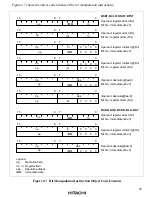
Figure 2.13 Stack before and after Interrupt Exception-Handling Sequence
2.7.4
Reset Start Timing
The reset start timing of the H8/3150 series, that is, the number of clock cycles between the rising
edge of
RES
and the reset vector fetch cycle, is a maximum of 200 external clock cycles.


