


136
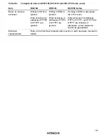
Table D.1
Comparison between H8/3102, H8/3103, and H8/3150 Series (cont)
Item
H8/3102
H8/3103
H8/3150 Series
EEPROM
Organization
32 bytes
×
256 pages
64 bytes
x 256 pages
H8/3152: 32 bytes x 264 pages
H8/3153: 64 bytes x 264 pages
H8/3155: 16 bytes x 72 pages
H8/3156: 16 bytes x 136 pages
H8/3158: 64 bytes x 264 pages
Low voltage
detection
indicator
(PWR bit)
Yes (when a low
voltage is detected,
bit 4 of ECR is set)
No* (when a low
voltage is detected,
the chip enters
reset state)
No* (when a low voltage is
detected, the chip enters reset
state)
I/O ports
2 (I/O-2 is not
multiplexed with
IRQ
)
2(I/O-2 is not
multiplexed with
IRQ
)
2(I/O-2 is multiplexed with
IRQ
)
RNG
No
No
Yes
WDT
No
No
Yes (option)
Interrupts
External interrupt:
One (I/O-1/
IRQ
)
External interrupt:
One (I/O-1/
IRQ
)
External interrupts:
Two (I/O-1/
IRQ
and I/O-2/
IRQ
)
Internal interrupts:
Two (WDT: EWE and UDF)
Internal clock
External clock/2
External clock/2
External clock or external clock/2
Power-down state
Sleep mode
Sleep mode
Sleep mode
Security
Low voltage
detector
Low frequency
detector
Low voltage
detector
Low frequency
detector
Illegal access
detector (when an
illegal access is
detected, EEPROM
access is disabled)
High frequency detector
High voltage detector
Low voltage detector
Low frequency detector
Illegal access detector (when an
illegal access is detected, the
chip enters reset state)
Note:
When a low voltage is detected, the PWR bit (bit 4 of ECR) is set to 1 in the H8/3102.
However, in the H8/3103 and H8/3150 series, bit 4 of ECR is a reserved bit and always
read as 1. Therefore, the PWR bit processing program for the H8/3102 must not be used for
the H8/3103 and H8/3150 series.


