


19
(8) Memory Indirect—@@aa:8: This mode can be used by the JMP and JSR instructions. The
second byte of the instruction code specifies an 8-bit absolute address. The word located at this
address contains the branch destination address.
The upper 8 bits of the absolute address are assumed to be 0 (H'00), so the address range is from
H'0000 to H'00FF (0 to 255). Note that addresses H'0000 to H'000D (0 to 13) are located in the
vector table.
If an odd address is specified as a branch destination or as the operand address of a MOV.W
instruction, the least significant bit is regarded as 0, causing word access to be performed at the
address preceding the specified address. See section 2.3.2, Memory Data Formats, for further
information.
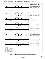
2.4.2
Effective Address Calculation
Table 2.2 shows how effective addresses are calculated in each of the addressing modes.
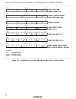
Arithmetic and logic instructions use register direct addressing (1). The ADD.B, ADDX, SUBX,
CMP.B, AND, OR, and XOR instructions can also use immediate addressing (6).
Data transfer instructions can use all addressing modes except program-counter relative (7) and
memory indirect (8).
Bit manipulation instructions use register direct (1), register indirect (2), or absolute (5) addressing
to specify a byte operand, and 3-bit immediate addressing (6) to specify a bit position in that byte.
The BSET, BCLR, BNOT, and BTST instructions can also use register direct addressing (1) to
specify the bit position.


