


16
/30
INSTALLATION OF OPTIONAL REMOTE CONTROLLER
16.9
FSG - FXG - G7 - HRG – USB/H-LINK CONNECTION
n
n
n
n
HARC40 WITH USB Connection
As a result of ISA Board connections being phased out of
Computer design, an
external Interface
with a
USB
connection, has been developed for H-Link connection to
the CS-NET. This also makes the application more flexible
in that it can be connected to a portable computer enabling
a service engineer to monitor systems which are not
connected to a CS-NET software.
The Installation must be carried out as detailed below.
?
NOTE:
All cables must be shielded and at least 0,75 mm²
cross section. Maximum length is 1000 m.
n
n
n
n
Installation
Install CS-NET program before start HARC installation.
Switch the computer off.
Connect the HARC40 Interface to the computer using the
USB connection cable.
Switch the computer on. Windows will automatically detect
that the Interface is connected and that the device
“HARCUSB” is available at the CD/CDROM. Windows will
automatically terminate the installation of the device.
Connect the CS-NET cable on the Interface to the H-Link
connection on any one of the indoor or Outdoor Units.
n
n
n
n
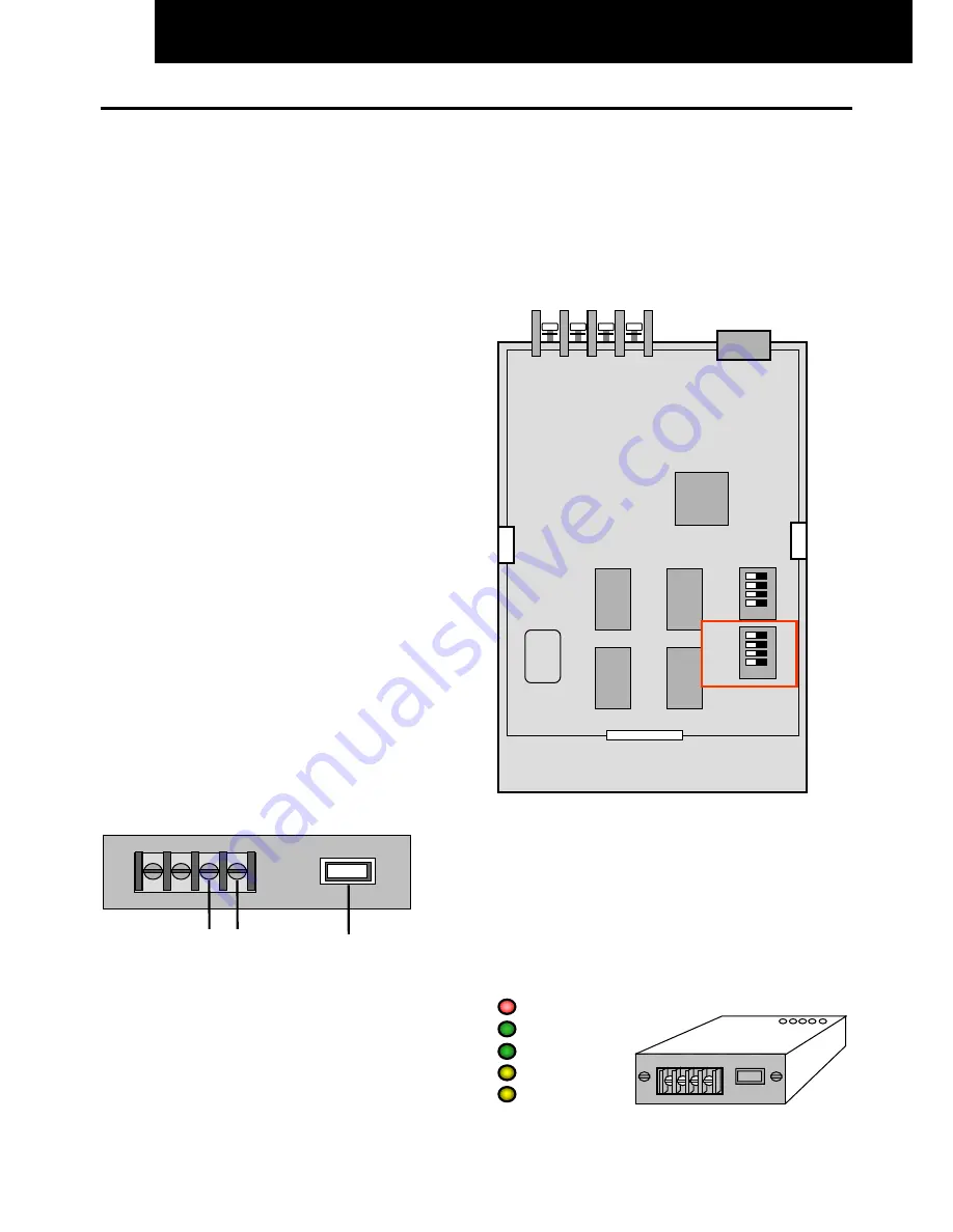
Interface Connections
The connections available for the Interface are as follows:
Terminal Board
TB1
(See diagram opposite
)
1. Main H-Link connection for 2-core cable to the system.
2. USB connection to the USB port on the computer.
The power supply for the HARC40 is taken through the
USB connection so no external supply is necessary
.
Rear View Of HARC40 Inter face
TB
1
USB
Connection
H-Link
n
n
n
n
HARC40 Interface Layout
The Layout of the HARC40 Interface printed circuit board,
as viewed from the underside, with the Dip Switch positions
and connections, can be seen opposite.
The Dip Switch
DSW1
must be set if more than one
Interface is installed. See Page 10 of this section for the
settings.
DSW2
must not be changed.
Input
H-Link to
System
USB
Connection
DSW1
DSW2
S1
S2
n
n
n
n
Led Indicators
POWER
Continuously lit when power from computer is
applied
USB
Blinks when transmission is available between
Computer and Interface
H-Link
Blinks when transmission is available between
Interface and the system
HARC1
Communication state (Not Used)
HARC2
Communication state (Not Used)
Power
USB
H-Link
HARC1
HARC2
Summary of Contents for FSG Series
Page 2: ......
Page 4: ......
Page 13: ...3 57 7 1 7 ...
Page 14: ......
Page 110: ......
Page 116: ......
Page 146: ......
Page 160: ...9 14 CONTROL SYSTEM n Cooling Operation FSG FSG1 cont ...
Page 162: ...9 16 CONTROL SYSTEM n Cooling mainly Cooling Operation FXG FXG1 cont ...
Page 163: ...CONTROL SYSTEM 9 17 9 6 3 DRY OPERATION FSG FSG1 I U Indoor Unit O U Outdoor Unit ...
Page 164: ...9 18 CONTROL SYSTEM n Dry Operation FSG FSG1 cont ...
Page 165: ...CONTROL SYSTEM 9 19 9 6 4 DRY OPERATION FXG FXG1 I U Indoor Unit O U Outdoor Unit ...
Page 166: ...9 20 CONTROL SYSTEM n Dry Operation FXG FXG1 cont ...
Page 167: ...CONTROL SYSTEM 9 21 9 6 5 HEATING OPERATION FSG FSG1 I U Indoor Unit O U Outdoor Unit ...
Page 168: ...9 22 CONTROL SYSTEM n Heating Operation FSG FSG1 cont ...
Page 170: ...9 24 CONTROL SYSTEM n Heating mainly Heating Operation FXG FXG1 cont ...
Page 171: ...CONTROL SYSTEM 9 25 n Defrosting Operation Control ...
Page 173: ...CONTROL SYSTEM 9 27 9 7 2 GAS BYPASS CONTROL 9 7 3 OVER HEATING PROTECTION CONTROL ...
Page 176: ...9 30 CONTROL SYSTEM 9 7 6 CONTROL FOR AUTO COOL HEAT OPERATION ...
Page 228: ......
Page 229: ...3 57 167 7 21 7 ...
Page 230: ......
Page 324: ......
Page 344: ......
Page 376: ......
Page 423: ......


