background image

SBX/SBXC/UBX/UBXC/FBX

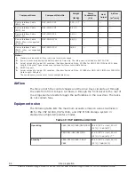
61 dB (24°C or less), 64 dB
(32°C), 70 dB (40°C) 

2

Notes:

1.

Measurement condition: The point 1m far from floor and surface of the product.

2.

The DKC-F810I-1R6FM/3R2FM and DKC-F710I-1R6FM/3R2FM cannot be used at 40°C.

Table 20  VSP F1500

Operating

CBXE/CBXF

58 dB (24°C or less), 60 dB
(32°C), 70 dB (40°C)

FBX

TBD

Standby 

3

CBXE/CBXF

58 dB (24°C or less), 60 dB
(32°C), 70dB (40°C)

FBX

TBD

Notes:

1.

Measurement condition: The point 1m far from floor and surface of the product.

2.

The DKC-F810I-1R6FM/3R2FM and DKC-F710I-1R6FM/3R2FM cannot be used at 40°C.

3.

Even if storage system is in a power-off state, the cooling fan continues to rotate in a standby
mode.

Power connection diagrams

The following figures show the correct way to connect the power distribution
units to the power distribution panels. When connected as shown, the system
operates normally if either AC inputs fails. In the following figures,
redundancy is provided through separate PDUs. These figures assume the
separate power distribution units are attached to independent PDUs.

Site preparation

89

Hitachi Virtual Storage Platform G1000, G1500, and Virtual Storage Platform F1500 Hardware Guide

Summary of Contents for F1500

Page 1: ...Hitachi Virtual Storage Platform G1000 G1500 and Virtual Storage Platform F1500 Hardware Guide MK 92RD8007 13 October 2016 ...

Page 2: ...s or otherwise from authorized employees and other individuals to access relevant data and 2 Verifying that data continues to be held retrieved deleted or otherwise processed in accordance with relevant laws Notice on Export Controls The technical data and technology inherent in this Document may be subject to U S export control laws including the U S Export Administration Act and its associated r...

Page 3: ...es 14 High performance 15 Scalability 16 Flexible connectivity 17 High reliability 17 High flexibility 17 Nondisruptive service and upgrades 19 High temperature mode 19 Economical and quiet 21 Hardware overview 21 Controller chassis 29 Controller components 30 Front end director 32 Supported connections and protocols 33 Flexible front end director installation 35 Supported speeds and cable lengths...

Page 4: ...g system support 63 Mainframe configuration 63 Systems operations 64 Compatibility and functionality 64 Systems host platform support 64 System configuration 65 Host modes and host mode options 65 Device Manager Storage Navigator 66 3 Safety requirements 69 General safety guidelines 70 Work safety guidelines 70 Warning about moving parts 71 Electrical safety guidelines 71 4 Site preparation 73 Saf...

Page 5: ...ures 110 Power on procedures 110 Power off procedures 111 Emergency power off on procedures 112 Emergency power off procedure 112 Power on procedure after emergency power off 112 Battery backup operations 112 Cache backup batteries 113 Battery life 114 Storing the system 114 6 Troubleshooting 117 Getting help 118 Solving problems 118 Service information messages SIM 118 A Specifications 121 Storag...

Page 6: ...81 C Regulatory compliance 183 Regulatory compliance 184 US FCC Notice 186 Electronic emissions testing 186 European Declaration of Conformity 187 Notice of export controls 187 China RoHS 187 Hazardous and toxic substances 188 Disposal 188 Recycling 188 Electronic emissions certificates 188 Glossary 193 Index 205 6 Hitachi Virtual Storage Platform G1000 G1500 and Virtual Storage Platform F1500 Har...

Page 7: ...storage systems and keep a copy to reference any information about the products Safety and environmental information Intended audience Product version Release notes Changes in this revision Related documents Document conventions Conventions for storage capacity values Accessing product documentation Getting help Comments Preface 7 Hitachi Virtual Storage Platform G1000 G1500 and Virtual Storage Pl...

Page 8: ...d the Hitachi Command Suite User Guide The concepts and functionality of storage provisioning operations in the use of Hitachi Dynamic Provisioning Hitachi Dynamic Tiering software Hitachi LUN Manager and Hitachi Data Retention Utility Product version This document revision applies to storage system microcode 80 05 0x or later Release notes Read the release notes before installing and using this p...

Page 9: ...e Shredder User Guide MK 92RD8025 For a list of all documents related to the Hitachi Virtual Storage Platform G1000 and G1500 and Hitachi Virtual Storage Platform F1500 storage systems see the Product Overview Document conventions This document uses the following typographic conventions Convention Description Bold Indicates text in a window including window titles menus menu options buttons fields...

Page 10: ...es helpful information guidelines or suggestions for performing tasks more effectively Caution Warns the user of adverse conditions and or consequences for example disruptive operations data loss or a system crash WARNING Warns the user of a hazardous situation which if not avoided could result in death or serious injury Conventions for storage capacity values Physical storage capacity values for ...

Page 11: ... sold by Hitachi Data Systems To contact technical support log on to Hitachi Data Systems Support Connect for contact information https support hds com en_us contact us html Hitachi Data Systems Community is a global online community for HDS customers partners independent software vendors employees and prospects It is the destination to get answers discover insights and make connections Join the c...

Page 12: ...12 Preface Hitachi Virtual Storage Platform G1000 G1500 and Virtual Storage Platform F1500 Hardware Guide ...

Page 13: ...cribes the hardware components of the VSP G1000 VSP G1500 and VSP F1500 storage systems System overview Hardware overview Introduction 13 Hitachi Virtual Storage Platform G1000 G1500 and Virtual Storage Platform F1500 Hardware Guide ...

Page 14: ...to the Hitachi Universal V2 Rack Reference Guide MK 94HM8035 Hitachi NAS Platform hardware accelerated network protocols support up to 2 GB sec throughput for sequential workloads and up to 1 2 million NFS operations per second Efficient caching makes up to 2 TB global cache dynamically accessible by all connected hosts and Hitachi NAS Platform nodes The HNAS file module provides primary data dedu...

Page 15: ...ces software logical partitioning along with simplified and unified data replication across heterogeneous storage systems Its large scale enterprise class virtualization layer combined with Hitachi Dynamic Tiering and thin provisioning software allows you to consolidate internal and external storage into one pool The storage system includes several features that improve system performance Hitachi ...

Page 16: ...n a system 3 HDS minimum cache per system is 64 GB whether the system contains one or two controllers Scalable storage capacity The minimum configuration is a single rack with one controller chassis in a diskless configuration A small system can be a single rack with one controller chassis and one or two drive chassis or flash drive chassis A mid sized system can be three racks with one controller...

Page 17: ...er chassis and drive chassis are configured in redundant pairs so that if any module fails the redundant module takes over until the failed component is replaced The redundant hardware includes power supplies VSD pairs cache path controllers front end directors back end directors and drives If one of these hardware components fails the storage system continues normal operation with zero data loss ...

Page 18: ... Maximum performance A storage system configured with only flash module drives delivers maximum performance This two controller system can contain 12 FMD chassis with a total of 576 flash module drives This system is designed for an on line retail site where customers expect fast access to multiple images or a hospital medical imaging system where physicians need immediate access to 3D CAT or MRI ...

Page 19: ... from Hitachi Global Solution Services GSS are required Contact your HDS authorized sales or service representative for more information High temperature mode High temperature mode is a feature that allows the storage system to operate at standard temperature 60 8 F to 89 6 F 16 C to 32 C or higher temperatures 60 8 F to 104 F 16 C to 40 C saving energy and cooling costs Temperature sensors at the...

Page 20: ...temperature mode See the System Administrator Guide for additional information Notify Technical Support Before enabling high temperature mode contact Hitachi Data Systems Support at https support hds com en_us contact us html for updates or additional information besides the following notes Guidelines for operating with flash module drives in high temperature mode Do not enable high temperature mo...

Page 21: ...ata center storage details 2252003 The speed of the fans in the controller and drive chassis is controlled by sensors in the units that measure the temperature of the exhaust air and set the fans to the speed necessary to maintain the unit temperature within a preset range When the system is less busy it generates less heat and fan speed is reduced saving energy and reducing the noise level Hardwa...

Page 22: ... controller and drive chassis within the racks For more information about system configurations contact your sales account representative Item Description 1 10U controller chassis 2 optional maximum of 12 8U FMD drive chassis 22 Introduction Hitachi Virtual Storage Platform G1000 G1500 and Virtual Storage Platform F1500 Hardware Guide ...

Page 23: ... max 384 max Table 3 Supported minimum configuration options Number of VSD pairs 1 2 or 3 4 5 6 or 7 8 No of controller chassis 1 1 1 2 2 2 Min cache memory GB 64 64 64 64 128 128 Cache Backup kit 1 1 1 1 2 2 front end directors 1 1 1 1 1 1 back end directors 0 0 0 0 0 0 Number of racks 1 1 1 1 1 1 Drive chassis SFF LFF FMD Optional Optional Optional Optional Optional Optional Assumes both control...

Page 24: ... DKC F810I PLUC DKC Power Cord Kit EU DKC F810I PLEC DKC F810I PLEC DKC F810I PLEC DKC F810I PLEC DKC Power Cord Kit China DKC F810I PLCC DKC F810I PLCC DKC F810I PLCC DKC F810I PLCC LFF Drive Chassis DKC F810I UBX DKC F810I UBXC DKC F810I UBX DKC F810I UBXC DKC F810I UBXC N A SFF Drive Chassis DKC F810I SBX DKC F810I SBXC DKC F810I SBX DKC F810I SBXC DKC F810I SBXC N A Drive Chassis Bezel DKC F81...

Page 25: ...MOD30 DKC F810I MOD30 DKC F810I MOD30 DKC F810I MOD30 Inter Controller Connecting Cable DKC F810I MFC30 DKC F810I MFC30 DKC F810I MFC30 DKC F810I MFC30 Inter Controller Connecting Kit DKC F810I MOD1J DKC F810I MOD1J DKC F810I MOD1J DKC F810I MOD1J Inter Controller Connecting Cable DKC F810I MFC1J DKC F810I MFC1J DKC F810I MFC1J DKC F810I MFC1J Device Interface Cable CC1 DKC F810I CC1 DKC F810I CC1...

Page 26: ... 16ML8 Mainframe Fibre 16 port 16G Host Adapter for Shortwave DKC F810I 16MS16 DKC F810I 16MS16 DKC F810I 16MS16 DKC F810I 16MS16 Mainframe Fibre 16 port 16G Host Adapter for Longwave DKC F810I 16ML16 DKC F810I 16ML16 DKC F810I 16ML16 DKC F810I 16ML16 FCOE 16 port Host Adapter DKC F810I 16FE10 DKC F810I 16FE10 DKC F810I 16FE10 DKC F810I 16FE10 iSCSI 8 port 10G Host Adapter DKC F810I 8IS10 DKC F810...

Page 27: ... ESCA DKC F810I ESCA DKC F810I ESCA FIPS140 2 Level2 Upgrade Toolkit DKC F810I FIPS2 DKC F810I FIPS2 DKC F810I FIPS2 DKC F810I FIPS2 Additional Processor Blades DKC F810I MP N A N A N A MP2 Upgrade Kit N A DKC F810I MP2UGH N A N A Additional Processor Blades 2 N A DKC F810I MP2 DKC F810I MP2 DKC F810I MP2 SFF 300 GB Disk Drive 15k DKC F810I 300KCM DKC F810I 300KCMC DKC F810I 300KCM DKC F810I 300KC...

Page 28: ...C F810I 6R0H9M DKC F810I 6R0H9M N A LFF 600 GB Disk Drive 10k DKC F810I 600J5M DKC F810I 600J5MC DKC F810I 600J5M DKC F810I 600J5MC N A N A LFF 400 GB SSD Drive DKC F810I 400M5M DKC F810I 400M5M N A N A 1 75 TB Flash Module Drive DKC F810I 1R6FN DKC F810I 1R6FN DKC F810I 1R6FN DKC F810I 1R6FN 3 5 TB Flash Module Drive DKC F810I 3R2FN DKC F810I 3R2FN DKC F810I 3R2FN DKC F810I 3R2FN 7 TB Flash Modul...

Page 29: ...th drives the controller also contains at least two back end director pair All components are installed in redundant pairs so that if any component fails the mirrored component will handle the load and the system will continue to run Any component including the operating system running on the SVP can be replaced or upgraded while the system is in operation Clusters The controller is logically divi...

Page 30: ...le BKM 2 4 Backup memory modules are installed in pairs and referred to as a backup memory kit Each module contains two batteries and either a 128 GB SSD flash drive small kit or a 256 GB SSD flash drive large kit If the power fails the cache is protected from data loss by the backup batteries and the cache flash memory SSD The batteries keep the cache active up to 32 minutes while the data is cop...

Page 31: ...back end directors and the cache backup memory It distributes data data routing function and sends hot line signals to the VSD The shared memory is located on the first CPA cache board in each cluster in the primary controller Figure 4 Controller rear view Table 6 Controller components rear Item Name Min Max Description 1 Power supply 2 4 200 240 VAC input Provides power to the controller chassis ...

Page 32: ...plication between the VSP G1000 VSP G1500 and VSP F1500 and other storage systems including communication between two Hitachi storage systems in a Global Active Device cluster See Front end director on page 32 for details 6 if diskless system 6 Cooling fan exhaust 5 5 The five exhaust fans on the rear of the controller pull hot air away from the components and push it out the back of the rack 7 FE...

Page 33: ...essed ON steady Link is available initialization complete but connection to the host has not been established Blinking when port is being accessed and data is being transferred between the host and the cache 3 Port Status FICON Dark off Green on OFF If system power is off port is not ready ON Link is available initialization has completed but connection to the host has not been established ON Link...

Page 34: ...cal signals from the FED to light pulses that are supported by the fiber optic cables Host connectors are either shortwave or longwave Fibre Channel FEDs are configured with shortwave host connectors by default Longwave host connectors are available and may be substituted as needed Item Description 1 Host connector lock lever Black lever shortwave Blue lever longwave Protocols An FED supports Fibr...

Page 35: ... me 16 8 per blade Target Contains two 8 port channel boards Each port contains a short wavelength multi mode host connector 16 port 16 Gbps FICON longwave adapter Mainfra me 16 8 per blade Target Contains two 8 port channel boards Each port contains an LC type long wavelength multi mode host connector 16 port 10 Gbps Fibre Channel over Ethernet FCoE Open 16 8 per blade Target Contains two 8 port ...

Page 36: ...k end directors and VSDs The following table shows the order of front end director FED installation If the storage system includes internal drives the controller requires a minimum of a single pair of back end directors and can be configured to support up to two back end directors The term standard describes a controller configured with a single back end director while high performance describes a...

Page 37: ...PD 2P D CHA1 1PK 2PK CHA7 1PD 2PD CHA1 1PK 2PK CHA7 1PD 2PD CHA1 1PK 2PK CHA7 3 1PE 2P E CHA2 MPB3 1PL 2PL CHA8 MPB7 1PE 2PE CHA2 MPB3 1PL 2PL CHA8 MPB7 1PE 2PE CHA2 MPB3 1PL 2PL CHA8 MPB7 4 1PF 2PF CHA3 MPB2 1PM 2PM CHA9 MPB6 1PF 2PF CHA3 MPB2 1PM 2PM CHA9 MPB6 1PF 2PF CHA3 MPB2 1PM 2PM CHA9 MPB6 5 1PB 2P B DKA1 CHA4 1PH 2PH DKA3 CHA10 1PB 2PB DKA1 CHA4 1PH 2PH DKA3 CHA10 6 1PA 2P A DKA0 CHA5 1PG...

Page 38: ... MPB7 4 1PF 2PF CHA3 MPB2 1PM 2PM CHA9 MPB6 1PF 2PF CHA3 MPB2 1PM 2PM CHA9 MPB6 1PF 2PF CHA3 MPB2 1PM 2PM CHA9 MPB6 5 1PB 2P B DKA1 CHA4 1PH 2PH DKA3 CHA10 1PB 2PB DKA1 CHA4 1PH 2PH DKA3 CHA10 6 1PA 2P A DKA0 CHA5 1PG 2PG DKA2 CHA11 1PG 2PG DKA2 CHA11 Note Intermixing of DKC F810I MP and DKC F810I MP2 is not supported Supported speeds and cable lengths The FEDs can be configured with either shortw...

Page 39: ...ntains two redundant power supplies and two ENC adapters that connect the drives to the controller The connection to the controller may be direct or it can be connected through other SFF drive trays See Figure 19 SAS Connection Diagram of Rack 00 SFF LFF Standard Model on page 94 LFF a 16U group of eight 2U drive trays Each holds up to 12 horizontally positioned 3 5 inch drives for a total of 96 d...

Page 40: ...F 2U drive tray diagram and front view Figure 7 LFF 2U drive tray diagram and front view Item Name Color Description 1 POWER LED Green OFF Power is not supplied to the system ON Power is supplied to the system READY LED Green OFF System is not operational 40 Introduction Hitachi Virtual Storage Platform G1000 G1500 and Virtual Storage Platform F1500 Hardware Guide ...

Page 41: ...ower is supplied to the system READY LED Green ON Normal operation Storage system is operational Fast blink Internal processing Storage system is operational Slow blink Offline download processing completed maintenance LOCATE LED Orange ON Nonfatal error Storage system can continue operating Contact technical support See Getting Help in the preface of this manual 2 ENC IN LED Green ON Port is conn...

Page 42: ...technical support See Getting Help in the preface of this manual 11 AC Socket For IEC60320 C14 plug 200 240 VAC 8 6 50 60 Hz Figure 9 FMD drive tray Item Description 1 Flash module Active LED Lights when the flash module is activated Blinks at drive access 2 Flash module Alarm LED Lights when the flash module has an error and should be replaced 3 SAS ENC Module Power LED 4 SAS ENC Module Alarm LED...

Page 43: ... DIMM must be installed in each CPA blade The memory modules in a system must all be the same size The following table shows minimum and maximum cache capacities per controller The figures are doubled for a two controller system Table 11 Cache capacities per controller of controller chassis configuration Capacity of cache memory module Maximum cache capacity configurable based on the number of cac...

Page 44: ... write data into the cache The amount of fast write data in cache is dynamically managed by the cache control algorithms to provide an optimum amount of read and write cache depending on the workload read and write I O characteristics Data protection The VSP G1000 VSP G1500 and VSP F1500 storage systems are designed to protect the loss of data or configuration information stored in the cache when ...

Page 45: ...GB or more less than 2 900 GB 15 GB or more 2 900 GB or more 16 GB or more 11 500 GB or more 22 GB or more 14 400 GB or more 24 GB or more 100 000 GB or more 30 GB or more 128 000 GB or more 32 GB or more 182 000 GB or more 40 GB or more 218 000 GB or more 48 GB or more 254 000 GB or more 56 GB or more 290 000 GB or more 64 GB or more 326 000 GB or more 72 GB or more Shared memory Shared memory ho...

Page 46: ...LDEV Apply Apply App ly Apply Apply Ap ply Apply 32 GB 1 255 64k LDEV Apply Apply App ly Apply Apply Ap ply Apply 32 GB 1 255 64k LDEV Apply Apply App ly Apply Apply Ap ply Apply 32 GB 1 64 16k LDEV Apply Apply Apply Apply Apply 40 GB 1 64 16k LDEV Apply Apply Apply App ly 40 GB 1 255 64k LDEV Apply Apply App ly Apply Apply Apply Ap ply Apply 40 GB 1 255 64k LDEV Apply Apply App ly Apply Apply App...

Page 47: ...4 GB 1 64 16k LDEV Apply Apply Apply Apply Apply App ly Apply 72 GB 1 255 64k LDEV Apply Apply App ly Apply Apply Apply App ly Apply Ap ply Apply 72 GB 1 255 64k LDEV Apply Apply App ly Apply Apply Apply App ly Apply Ap ply Apply 72 GB 1 255 64k LDEV Apply Apply App ly Apply Apply Apply Apply App ly Apply Ap ply Apply 80 GB 1 Software includes the following applications SI ShadowImage HDP Hitachi ...

Page 48: ...ata from its corresponding CPA blade and no data is lost In the unlikely event where a CFM has failed and a full power failure occurs the other CFM backs up the mirrored data from the CPA without any loss of data Cache flash memory capacity The recommended size of the installed cache flash memory depends on the size of the cache memory and is automatically selected when defining the configuration ...

Page 49: ...sizes must be the same in all CFM Cache must be distributed evenly across CFMs and controllers Note The small CFM SSDs 128 GB can be installed in the large cache backup allowing for easier and less expensive upgrades Introduction 49 Hitachi Virtual Storage Platform G1000 G1500 and Virtual Storage Platform F1500 Hardware Guide ...
Page 50: ...50 Introduction Hitachi Virtual Storage Platform G1000 G1500 and Virtual Storage Platform F1500 Hardware Guide ...
Page 51: ... System architecture overview Hardware architecture VSP G1000 VSP G1500 and VSP F1500 RAID implementation CU images LVIs and logical units Mainframe operations Systems operations Host modes and host mode options Device Manager Storage Navigator Hardware architecture 51 Hitachi Virtual Storage Platform G1000 G1500 and Virtual Storage Platform F1500 Hardware Guide ...

Page 52: ...k end directors disk adapters providing processing power where and when it is needed without wait time or interruption This significantly increases the I O throughput up to three times the speed of the VSP system The system provides a highly granular upgrade path allowing the addition of drives to the drive chassis and components such as virtual storage directors to the controller chassis as stora...

Page 53: ...1 consists of the drives highlighted by yellow rectangles RAID group 2 is shown by the red rectangles Figure 10 RAID group example In the above figure the drives with the red rectangles are unformatted physical drives so they are called an array group The drives with the yellow rectangles have been formatted as a RAID level and have initial parity data on them so they are called a parity group Gen...

Page 54: ...l data is written to the primary and secondary disk drives The data is distributed on the two RAID pairs Advantage RAID 1 is highly usable and reliable because of the duplicated data It has higher performance than ordinary RAID 1 when it consists of two disk drives because it consists of the two RAID pairs Disadvantage Requires disk capacity twice as large as the user data 54 Hardware architecture...

Page 55: ...unk contains either eight logical tracks mainframe or 768 logical blocks open This RAID 5 implementation minimizes the write penalty incurred by standard RAID 5 implementations by keeping write data in cache until the entire stripe can be built and then writing the entire data stripe to the drives The 7D 1P RAID 5 configuration increases usable capacity and improves performance The following two f...

Page 56: ...cess because each disk can receive I O instructions independently It can provide high reliability and usability at a comparatively low cost by virtue of the parity data Disadvantage Write penalty of RAID 5 is larger than that of RAID 1 because pre update data and pre update parity data must be read internally as the parity data is updated when data is updated 56 Hardware architecture Hitachi Virtu...

Page 57: ...ipe on page 58 shows RAID 5 data stripes mapped across four physical drives Data and parity are striped across each drive in the array group hence the term parity group The logical devices LDEVs are dispersed evenly in the array group so that the performance of each LDEV within the array group is the same This figure also shows the parity chunks that are the Exclusive OR XOR of the data chunks The...

Page 58: ...n up to two drives in an array group fail Therefore RAID 6 is the most reliable of the RAID levels The following figure illustrates the RAID 6 configuration and the table describes the configuration Note There are two configurations of RAID 6 6D 2P configuration eight disk drives and 14D 2P configuration sixteen disk drives The following diagram shows the 6D 2P configuration 58 Hardware architectu...

Page 59: ...across multiple RAID5 array groups for improved logical unit performance in Open system environments The advantages of LDEV striping are Improved performance especially of an individual logical unit due to an increase in the number of drives that constitute an array group Superior workload distribution If the workload of one array group is higher than another array group you can distribute the wor...

Page 60: ...Figure 12 LDEV Striping Across 2 RAID5 7D 1P Array Groups 60 Hardware architecture Hitachi Virtual Storage Platform G1000 G1500 and Virtual Storage Platform F1500 Hardware Guide ...

Page 61: ...nits This section provides information about control unit images logical volume images and logical units CU images The storage system is configured with one control unit image for each 256 devices one SSID for each 64 or 256 LDEVs and supports a maximum of 255 CU images in the primary logical disk controller LDKC Hardware architecture 61 Hitachi Virtual Storage Platform G1000 G1500 and Virtual Sto...

Page 62: ...installed LVI range of 00 to FF For maximum flexibility in LVI configuration the storage system provides the Virtual LVI feature Using Virtual LVI users can configure multiple LVIs under a single LDEV For further information on Virtual LVI see the Provisioning Guide for Mainframe Systems Logical units The storage system is configured with OPEN V logical unit types The OPEN V logical unit can vary ...

Page 63: ...ions See the following user documents for information and instructions about configuring your storage system for Mainframe operations The Mainframe Host Attachment and Operations Guide describes and provides instructions for configuring the storage system for Mainframe operations including FICON attachment hardware definition cache operations and device operations For detailed information about FI...

Page 64: ...cing with the appropriate middleware support such as HGLM without sacrificing cache coherency Users should plan for path failover alternate pathing to ensure the highest data availability The logical units can be mapped for access from multiple ports or multiple target IDs The number of connected hosts is limited only by the number of FC ports installed and the requirement for alternate pathing wi...

Page 65: ...s and LUN security Each Fibre Channel port on the storage system provides addressing capabilities for up to 2 048 LUNs across as many as 255 host groups each with its own LUN 0 host mode and host mode options Multiple host groups are supported using LUN security The Hitachi SNMP Agent User Guide describes the SNMP API interface for the storage systems and provides instructions for configuring and ...

Page 66: ...onfiguration and status information and sends user initiated commands to the storage system The Device Manager Storage Navigator displays detailed storage system information and allows users to configure and perform storage operations on the system Device Manager Storage Navigator is provided as a Java applet program that can be executed on any machine that supports a Java Virtual Machine JVM A PC...

Page 67: ...Figure 14 Device Manager Storage Navigator and SVP Configuration Hardware architecture 67 Hitachi Virtual Storage Platform G1000 G1500 and Virtual Storage Platform F1500 Hardware Guide ...
Page 68: ...68 Hardware architecture Hitachi Virtual Storage Platform G1000 G1500 and Virtual Storage Platform F1500 Hardware Guide ...

Page 69: ... additional safety information that may apply to your facility Read and follow the safety guidelines in this chapter before installing the equipment The key sections in this chapter include General safety guidelines Work safety guidelines Safety requirements 69 Hitachi Virtual Storage Platform G1000 G1500 and Virtual Storage Platform F1500 Hardware Guide ...

Page 70: ... cautions and instructions in various languages are attached to the storage system components The safety warnings provide guidelines to follow when working with any equipment Before working on the storage system read all safety and warning labels attached to it If the labels become dirty damaged unreadable or peel off contact the Hitachi Data Systems support center Authorized personnel Allow only ...

Page 71: ...ble injury when working with authorized service personnel Observe the following warning related to moving parts Tuck in any loose clothing so that it cannot be caught by a moving or rotating part such as a fan Tie up long hair Unless otherwise specifically instructed do not supply power to any device that contains rotating or moving parts that are not properly covered Electrical safety guidelines ...

Page 72: ...e there are no potential electric hazards in the maintenance area such as insufficient grounding or a wet floor 72 Safety requirements Hitachi Virtual Storage Platform G1000 G1500 and Virtual Storage Platform F1500 Hardware Guide ...

Page 73: ...formation including specifications for all possible installations If you need additional information contact customer support Safety requirements Responsibilities Site preparation checklist General site requirements Data center requirements Operational requirements System specifications and requirements Power connection diagrams Data connection diagrams Long cable connections Port configurations S...

Page 74: ... the information in this manual to determine the specific requirements for your installation As needed review the to familiarize yourself with the components features and functions of the storage system Verify that the installation site meets all installation requirements A checklist is included in this section to help you with this task Provide electrical hardware including cables connectors and ...

Page 75: ... installed in a Hitachi rack when delivered or assembled on site The delivered equipment may include only the system components if the customer supplies a standard 19 inch rack Rack specifications are contained in the Hitachi Universal V2 Rack Reference Guide MK 94HM8035 Location The specific location in the data center area or footprint on the floor where the storage system will be installed User...

Page 76: ...uirements See Data center requirements on page 78 Does the data center have a raised floor Does the location meet the requirements for service clearance and cable routing for example floor cutouts See Equipment clearances on page 77 Does the installation site meet the floor load rating requirements Power Requirements See Electrical specifications on page 81 Does the data center meet the AC input p...

Page 77: ... dock to the installation location in the data center Equipment clearances Receiving area The receiving dock storage area and receiving area must be large enough to allow movement of and access to crated or packed equipment Other areas The hallways doorways ramps and elevators must be wide enough to allow a single unpacked rack to be moved to the installation location If there is insufficient spac...

Page 78: ...em storage requirements If the equipment must be stored after delivery and prior to installation the storage location must meet the storage environmental requirements for the storage system See Table 18 VSP G1000 VSP G1500 and VSP F1500 environmental specifications on page 83 for specifications Data center requirements The data center must meet the following general requirements Detailed mechanica...

Page 79: ...end directors The following table lists the cable length requirements for the front end directors in the storage system Table 14 Maximum cable length short wave DataTransf erRate OM2 50 125 f m multi mode fiber OM3 50 125 f m laser optimizedmulti mode fiber OM4 50 125 f m laser optimizedmulti mode fiber MB s feet meters feet meters feet meters 200 984 3 300 1640 4 500 400 492 1 150 1246 7 380 1312...

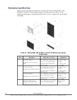
Page 80: ...us space in rack 309 lb 140 kg empty 377 lb 171 kg fully loaded 2 SFF Drive chassis Supports up to eight 2U trays 33 in 838 mm x 19 in 483 mm x 26 in 711 2 mm Requires 16U of contiguous space in rack 315 lb 143 kg empty 443 lb 201 kg fully loaded LFF Drive Chassis Supports up to eight 2U trays 33 in 838 mm x 19 in 483 mm x 26 in 711 2 mm Requires 16U of contiguous space in rack 300 lb 136 kg empty...

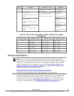
Page 81: ... 3600 47 25 1200 79 1 2010 Electrical specifications Note The current and power specifications in the following tables were measured on the following VSP G1000 VSP G1500 and VSP F1500 storage systems in a controlled environment To calculate the power draw current draw and heat output of a specific system see Component weight heat airflow and power consumption on page 84 or easier use the Power and...

Page 82: ...he receptacles in the vicinity of the unit or system must include a ground connection The grounding conductors serving these receptacles must be connected to earth ground at the service equipment or other acceptable building earth ground Power connection The AC power input for the storage system has a duplex PDU structure that allows the rack installed equipment to remain powered on if power is re...

Page 83: ...0 8 to 104 16 to 40 Relative Humidity 4 20 to 80 8 to 90 5 to 95 Max Wet Bulb ºF ºC 78 8 26 80 6 27 84 2 29 Temperature deviation per hour ºF ºC 50 10 50 10 68 20 Vibration6 5 to 10Hz 0 25 mm10 to 300Hz 0 49m s2 5 to 10Hz 2 5mm10 to 70Hz 4 9m s270 to 99Hz 0 05mm99 to 300Hz 9 8m s2 Sine Vibration 4 9m s2 5min At the resonant frequency with the highest displacement found between 3 to 100Hz7 Random V...

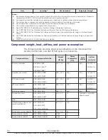
Page 84: ...re installed Component weight heat airflow and power consumption The following table provides physical specifications of the individual VSP G1000 VSP G1500 and VSP F1500 system components Component Name Component Model No Weight lb Kg Power Consumption VA Heat Output Airflow m3 min Primary controller DKC810I CBXA DKC810I CBXAC4 DKC810I CBXE4 312 142 508 1 483 1 16 7 32 C 25 9 40 C Secondary contro...

Page 85: ...SAS LFF disk drive DKC F810I 4R0H3M DKC F810I 4R0H3MC4 0 83 0 83 14 84 600GB 10K rpm disk drive in LFF canister DKC F810I 600J5M DKC F810I 600J5MC4 0 66 0 3 14 84 6TB 7 2K rpm SAS LFF disk drive DKC F810I 6R0H9M4 1 9 0 86 14 84 400GB MLC SSD in LFF canister DKC F810I 400M5M 0 66 0 3 7 14 400GB SFF MLC SSD DKC F810I 400MCM 0 29 0 13 6 74 800GB SFF MLC SSD DKC F810I 800MCM 0 29 0 13 6 74 Hitachi Acc...

Page 86: ...ibre 16 port 16G front end director for Shortwave DKC F810I 16MS16 5 3 2 4 130 137 Mainframe Fibre 16 port 8G front end director for Longwave DKC F810I 16ML8 5 3 2 4 120 126 Mainframe Fibre 16 port 16G front end director for Longwave DKC F810I 16ML16 5 3 2 4 130 137 SFP for 8Gbps Longwave DKC F810I 1PL8 0 02 SFP for 8Gbps Shortwave DKC F810I 1PS8 0 02 SFP for 16Gbps Longwave DKC F810I 1PL16 0 02 S...

Page 87: ...LEC 2 0 7 Power Cord Kit SFF LFF drive chassis EU DKC F810I PHEC 6 8 3 1 Power Cord Kit FMD drive chassis EU DKC F810I PFEC 3 1 1 4 Power Cord Kit controller chassis China DKC F810I PLCC 1 5 0 7 Power Cord Kit SFF LFF drive chassis China DKC F810I PHCC 6 6 3 0 Power Cord Kit FMD drive chassis China DKC F810I PFCC 2 9 1 3 Inter Controller Connecting Kit 5 m DKC F810I MOD5 4 4 2 0 1 Inter Controller...

Page 88: ...t a typical I O condition Random Read and Write 50 IOPSs for HDD 2500 IOPSs for SSD FMD Data Length 8Kbytes These values may increase for future compatible drives Airflow The fans in both the control chassis and the drive trays circulate air through the units from front to back Air flows in through the front bezel to the rear of the component and exits through the perforations in the rear door The...

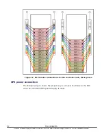
Page 89: ...e DKC F810I 1R6FM 3R2FM and DKC F710I 1R6FM 3R2FM cannot be used at 40 C 3 Even if storage system is in a power off state the cooling fan continues to rotate in a standby mode Power connection diagrams The following figures show the correct way to connect the power distribution units to the power distribution panels When connected as shown the system operates normally if either AC inputs fails In ...

Page 90: ...Figure 15 Direct power connection 90 Site preparation Hitachi Virtual Storage Platform G1000 G1500 and Virtual Storage Platform F1500 Hardware Guide ...
Page 91: ...m do not cross connect the AC cables as shown in the above illustration Otherwise a system failure can occur when either of the AC inputs is interrupted Site preparation 91 Hitachi Virtual Storage Platform G1000 G1500 and Virtual Storage Platform F1500 Hardware Guide ...

Page 92: ...ee phase UPS power connection The following figure shows the proper way to connect the PDUs to the PDP when an uninterruptible power supply is used 92 Site preparation Hitachi Virtual Storage Platform G1000 G1500 and Virtual Storage Platform F1500 Hardware Guide ...

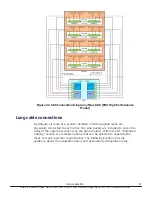
Page 93: ...rol cables between the control chassis and the drive chassis in the block module and between the controller and HNAS storage in the file module The following illustrations show the correct way to connect the drive chassis to the controller Site preparation 93 Hitachi Virtual Storage Platform G1000 G1500 and Virtual Storage Platform F1500 Hardware Guide ...

Page 94: ...Figure 19 SAS Connection Diagram of Rack 00 SFF LFF Standard Model 94 Site preparation Hitachi Virtual Storage Platform G1000 G1500 and Virtual Storage Platform F1500 Hardware Guide ...
Page 95: ...Figure 20 SAS Connection Diagram of Rack 00 SFF LFF High Performance Model Site preparation 95 Hitachi Virtual Storage Platform G1000 G1500 and Virtual Storage Platform F1500 Hardware Guide ...

Page 96: ...Figure 21 SAS Connection Diagram of Rack 00 FBX Standard Model 96 Site preparation Hitachi Virtual Storage Platform G1000 G1500 and Virtual Storage Platform F1500 Hardware Guide ...

Page 97: ...ncluded to cover the sides of the outermost racks see the figure below Within the R1 Extended Cabling section are multiple options that can be selected to separate the racks to meet customer requirements The following sections provide guidance about the available options and associated configuration rules Site preparation 97 Hitachi Virtual Storage Platform G1000 G1500 and Virtual Storage Platform...

Page 98: ...racks are not physically attached to each other the Hitachi Configurator asks you to specify the length of cable for connecting the two controllers Cable length options are 5 meters which is the standard length 30 meters and 100 meters The following figure shows a dual controller configuration with extended cabling between the racks containing the two controllers The Configurator includes addition...

Page 99: ... containing the primary controller and two drive chassis and rack R1 containing two drive chassis In addition extended cabling between racks R1 and R2 is available The Configurator includes additional side panels as required While not shown in the following figure extending the cabling between racks in a dual controller configuration is also supported To avoid I O latency issues the sum of the len...

Page 100: ...tween rack L0 containing the secondary controller and rack L1 containing two drive chassis The Configurator includes additional side panels as required While not shown in the following figure the configuration can include an R2 rack directly connected to or separated from the R1 rack Similarly the configuration can include an L2 rack directly connecting to or separating from the L1 rack To avoid I...

Page 101: ...rt the SAS optical cables is V02 DKCMAIN 80 02 01 00 01 released October 20 2014 You are strongly encouraged to keep your storage system microcode level current to ensure you have the most up to date enhancements and fixes If your storage systems is using an earlier microcode release contact your authorized service provider for assistance with planning ordering and installing a more current microc...

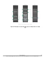
Page 102: ...Figure 27 Example of a dual controller option 1 configuration in a single rack 102 Site preparation Hitachi Virtual Storage Platform G1000 G1500 and Virtual Storage Platform F1500 Hardware Guide ...

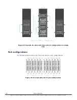
Page 103: ...Figure 28 Example of a dual controller option 2 configuration in a single rack Site preparation 103 Hitachi Virtual Storage Platform G1000 G1500 and Virtual Storage Platform F1500 Hardware Guide ...

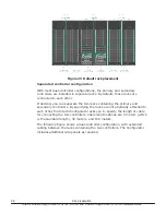
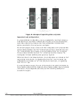
Page 104: ...single rack Port configurations The following figures show the front end director port configurations Figure 30 front end director 16 port configuration 104 Site preparation Hitachi Virtual Storage Platform G1000 G1500 and Virtual Storage Platform F1500 Hardware Guide ...
Page 105: ...Figure 31 front end director 8 port configuration Site preparation 105 Hitachi Virtual Storage Platform G1000 G1500 and Virtual Storage Platform F1500 Hardware Guide ...
Page 106: ...106 Site preparation Hitachi Virtual Storage Platform G1000 G1500 and Virtual Storage Platform F1500 Hardware Guide ...

Page 107: ...e recommended procedures to use in the case of a power failure Safety and environmental information Power control panel System idle mode Normal power on off procedures Emergency power off on procedures Battery backup operations Power on off procedures 107 Hitachi Virtual Storage Platform G1000 G1500 and Virtual Storage Platform F1500 Hardware Guide ...
Page 108: ...Table 21 Storage system power controls and status indicators Item Description 1 REMOTE MAINTENANCE switch Set to ENABLE to allow remote maintenance Set to DISABLE to prevent remote maintenance 2 ENABLE switch Used to enable the PS ON PS OFF switch See Power on procedures on page 110 3 POWER switch Move up or down to turn system power on or off See Power on procedures on page 110 4 READY LED indica...

Page 109: ... storage system power cables are plugged into the PDUs and the PDU breakers are on the storage system is in idle basic supply only mode When the storage system is in idle mode The amber Basic Supply BS LED on the control panel is on This indicates that AC power is applied to the power supplies The green READY LED is off This indicates that the controller and drive chassis are not operational The f...

Page 110: ...s the ENABLE switch is moved to and held in the ENABLE position while the power switch is moved to the ON or OFF position Perform the procedure to turn on the storage system If applicable refer to the figure of the control panel in Figure 32 Storage system control panel on page 108 Procedure 1 On the control panel check the amber BS LED and make sure it is lit It indicates that the storage system ...

Page 111: ...cache backup flash memory When the cache backup batteries discharge power the power on time may be prolonged by the amount of charge remaining in the batteries Fully discharged batteries take 90 minutes to charge Note The control panel includes a safety feature to prevent the storage system power from being turned on or off accidentally The PS power ON OFF switch does not work unless the ENABLE sw...

Page 112: ... units and in any order turn off the circuit breakers to all the PDUs Power on procedure after emergency power off To turn the power on to the storage system after an emergency shutdown use the following instructions Procedure 1 In all system racks turn on the circuit breakers in the PDUs supplying electrical power to the drive units 2 In both controller racks turn on the circuit breakers in the P...

Page 113: ...m continues to operate for 20 milliseconds and detects the power failure 3 The cache memory data and storage system configuration are backed up to the cache flash memory in the cache backup assemblies If power is restored during the backup the backup stops unless the backup battery capacities are used less than 50 In case the system operates in write through mode until the batteries are charged en...

Page 114: ...must be connected to power for three hours to fully recharge Note The storage system generates a SIM when the cache backup batteries are not charged to at least 50 The LEDs on the front panel of the cache backup kits also show the status of the batteries Storing the system While connected the cache backup batteries will completely discharge in two to three weeks without power applied If you are no...

Page 115: ... long term storage contact technical support and request a disconnection of the battery jumpers on the cache boards Power on off procedures 115 Hitachi Virtual Storage Platform G1000 G1500 and Virtual Storage Platform F1500 Hardware Guide ...

Page 116: ...116 Power on off procedures Hitachi Virtual Storage Platform G1000 G1500 and Virtual Storage Platform F1500 Hardware Guide ...

Page 117: ...ovides troubleshooting information for the storage system Getting help Solving problems Service information messages SIM Troubleshooting 117 Hitachi Virtual Storage Platform G1000 G1500 and Virtual Storage Platform F1500 Hardware Guide ...
Page 118: ... on the power to the storage system If necessary contact customer support for assistance Fence message is displayed on the console Determine whether there is a failed storage path If a failed storage path occurred toggle the RESTART switch and retry the operation If the fence message displays again contact customer support for assistance READY LED does not go on or there is no power supplied Conta...

Page 119: ...rate serious and acute The service and moderate SIMs lowest severity do not require immediate attention and are addressed during routine maintenance The serious and acute SIMs highest severity are reported to the host system once every eight hours Note If a serious or high level SIM is reported contact the support center immediately to ensure the problem is being addressed The following figure ill...

Page 120: ...120 Troubleshooting Hitachi Virtual Storage Platform G1000 G1500 and Virtual Storage Platform F1500 Hardware Guide ...
Page 121: ...for the VSP G1000 VSP G1500 and VSP F1500 storage systems Storage system specifications Mechanical specifications Electrical specifications Environmental specifications PDU specifications Specifications 121 Hitachi Virtual Storage Platform G1000 G1500 and Virtual Storage Platform F1500 Hardware Guide ...

Page 122: ...tem Number of drives Minimum 4 disk in model 0 diskless model Maximum 2 304 SFF HDD 1 152 LFF HDD Maximum number of flash drives 384 6 Maximum number of flash module drives 576 RAID level RAID 6 RAID 5 RAID 1 RAID Group Configuration RAID 6 6D 2P 14D 2P RAID 5 3D 1P 7D 1P RAID 1 2D 2D 4D 4D Maximum number of spare drives 96 1 Maximum number of volumes 65 280 Maximum storage system capacity physica...

Page 123: ...4 C or less 64dB 32 C 70dB 40 C 7 Standby 5 CBXA CBXAC CBXB CBXE CBXF 58dB 24 C or less 60dB 32 C 70dB 40 C SBX SBXC UBX UBXC FBX 61dB 24 C or less 64dB 32 C 70dB 40 C 7 Dimension W x D x H mm Single rack 610 x 1 115 x 2 006 Six racks 3 610 x 1 115 x 2 006 Non stop maintenance Control PCB Support Cache memory module Support Cache flash memory Support Power supply fan Support Microcode Support Driv...

Page 124: ...ure Hierarchical Star Net Maximum bandwidth Data path 768 GBps Control path 128 GBps Memory Cache memory capacity 128 GB to 2 048 GB Cache flash memory capacity 256 GB to 2 048 GB Device I F DKC DKU Interface SAS Dual Port Data Transfer Rate Max 6 Gbps Maximum Number of Drive per SAS I F Under the FMD Standard Model 72 Maximum Number of DKA 4 Channel I F Support channel type Mainframe 2 4 8 Gbps F...

Page 125: ... port on the CHA to the DKC F810I 1PL8 the port can be used for the long wavelength 3 By the replacing SFP transceiver of the fibre port on the CHA to the DKC F810I 1PL16 the port can be used for the long wavelength 4 Measurement Condition The point 1m far from floor and surface of the product 5 Even if storage system is in a power off state the cooling fan continues to rotate in a standby mode 6 ...

Page 126: ...neration 1 6 TB FMD DC2 drive as a spare Array group consisting of 3 2 TB FMD DC2 requires the same generation 3 2 TB FMD DC2 drive as a spare Array group consisting of 6 4 TB FMD DC2 requires the same generation 6 4 TB FMD DC2 drive as a spare Maximum Number of Drives Drive type inches Drive chassis Max per drive chassis Max per 2 controller system HDD 2 5 SFF 192 2 304 HDD 3 5 LFF 96 1 152 FMD 5...

Page 127: ...rives 3 181 1 446 576 LFF drives 6 362 2 892 1 152 LFF drives Electrical specifications The VSP G1000 VSP G1500 and VSP F1500 storage system PDUs support both single phase or three phase AC power The system components use single phase 220 VAC Table 28 Input power specifications Item Input Power to PDUs Input Current 1 Steady Current 2 Leakage Current Inrush Current 1st 0 p 2nd 0 p 1st 0 p Time 25 ...

Page 128: ...C system is not supported Power Supply Locations Note Depending on the configuration the storage system may draw considerably less power than the rating of the PDU plugs Use the weight and power calculator to determine the power draw for a specific system See the note under Electrical specifications on page 81 128 Specifications Hitachi Virtual Storage Platform G1000 G1500 and Virtual Storage Plat...

Page 129: ...ifications Detailed PDU specifications are located in Appendix C See PDU specifications on page 131 2 Americas Single phase 30 Amp PDU 12 IEC C13 EMEA APAC Single phase 32 Amp PDU 12 IEC C13 2 IEC C19 3 Americas Methode three phase 30 Amp PDU 24 IEC C13 6 IEC C19 EMEA APAC Minkels three phase 32 Amp PDU 24 IEC C13 6 IEC C19 Environmental specifications The following table lists the specifications ...

Page 130: ...operation should be met before the storage system is powered on Maximum temperature of 90 F 32 C at air system air inlet should be strictly met 2 Unless otherwise specified non operating condition includes both packing and unpacking conditions 3 The system and components should be packed in factory packing for shipping and storing 4 No condensation in and around the drives should be observed under...

Page 131: ...ode 60 8 to 77 16 to 25 4200 57 4 77 to 89 6 25 to 32 4700 59 5 high temperature mode ºF ºC 89 6 to 104 32 to 40 7400 69 3 PDU specifications For information about PDUs refer to the Hitachi Universal V2 Rack Reference Guide Specifications 131 Hitachi Virtual Storage Platform G1000 G1500 and Virtual Storage Platform F1500 Hardware Guide ...

Page 132: ...132 Specifications Hitachi Virtual Storage Platform G1000 G1500 and Virtual Storage Platform F1500 Hardware Guide ...

Page 133: ...des This appendix lists and describes the public system option modes System option modes SOM details System option modes 133 Hitachi Virtual Storage Platform G1000 G1500 and Virtual Storage Platform F1500 Hardware Guide ...

Page 134: ...84 operational specifications on page 180 Table 38 SOM 729 behavior on page 179 Table 39 SOM 784 operational specifications on page 180 Table 40 SOM 803 behavior on page 180 Table 41 SOM 855 behavior with SOM 467 on page 180 Table 42 Relations among SOM897 SOM898 and SOM901 on page 180 Table 43 Relations between SOM930 SOM755 and SOM859 on page 181 Note The following tables were up to date at the ...

Page 135: ...opy in case ECCs LRC PINs are set on the track of copy source HDD mode 22 can be used to interrupt the copy processing default or to create ECCs LRC PINs on the track of copy target HDD to continue the processing Mode 22 ON If ECCs LRC PINs up to 161 have been set on the track of copy source HDD ECCs LRC PINs up to 161 will be created on the track of copy target HDD so that the copy processing wil...

Page 136: ...ure Suspend occurs while the Freeze Option Enable is set except the pair in which the Failure Suspend occurs other pairs that fulfill the conditions below go into SCP state Conditions TrueCopy Sync M VOL Mainframe Volume Pair status Duplex Pending A pair whose RCU is identical to the RCU for which the Freeze command is specified Notes 1 When all the following conditions are met set Mode 64 ON 2 Wh...

Page 137: ...differs depending on the Normal or Quick specification OFF 87 ShadowImage Determines whether NormalCopy or QuickResync if not specified is performed at the execution of pairresync by CCI Mode 87 ON QuickResync is performed Mode 87 OFF NormalCopy is performed OFF 104 HRC Changes the default CGROUP Freeze option OFF MCU 114 HRC This mode enables or disables the LCP RCP port to be automatically switc...

Page 138: ...fter specifying Split Resync following the mode setting The mode function does not work if it is set during the Split Resync operation OFF 187 Common Yellow Light Option only for XP product OFF 190 HRC TCz Allows you to update the VOLSER and VTOC of the R VOL while the pair is suspended if both mode 20 and 190 are ON OFF RCU 269 Common High Speed Format for CVS Available for all dku emulation type...

Page 139: ...ching the port attribute reset the Chip without issuing the OLS OFF MCU RCU 305 Mainframe This mode enables the pre label function creation of VTOC including VOLSER Mode 305 ON Pre label function is enabled Notes 1 Set SOM 305 to ON before performing LDEV Format for a mainframe volume if you want to perform OS IPL volume online without fully initializing the volume after the LDEV Format However fu...

Page 140: ...al Replicator Universal Replicator for Mainframe Mode 448 ON Enabled If the SVP detects a blocked path the SVP assumes that an error occurred and then immediately splits suspends the mirror Mode 448 OFF Disabled If the SVP detects a blocked path and the path does not recover within the specified period of time the SVP assumes that an error occurred and then splits suspends the mirror Note The mode...

Page 141: ...ore set Mode 454 to OFF in most cases Mode 454 ON The amount of the entire destage processing is periodically determined by using the workload of the entire system b The larger the workload is the larger the amount of the entire destage processing becomes b Write Pending capacity of the entire system Cache capacity of the entire system Because the destage processing would not be accelerated even i...

Page 142: ...e data is not fixed current spec OFF 466 Universal Replicator Universal Replicator for Mainframe For UR URz operations it is strongly recommended that the path between main and remote storage systems have a minimum data transfer speed of 100 Mbps If the data transfer speed falls to 10 Mbps or lower UR operations cannot be properly processed As a result many retries occur and UR pairs may be suspen...

Page 143: ...y on Write Snapshot Hitachi Thin Image 70 05 0x 00 00 or higher Since the SIM RC 601xxx that are generated when the usage rate of Pool used by Snapshot exceeds the threshold value can be resolved by users basically they are not reported to the maintenance personnel This option is used to inform maintenance personnel of these SIMs that are basically not reported to maintenance personnel in case the...

Page 144: ...I O Therefore the processing speed of the update I O slows down by about 15µs per command 3 If this mode is set to ON the processing speed of update I O slows down by about 15µs per command version downgrade is disabled and Take Over is not available 4 If the mode is not set to ON for both or either sides the behavior is as follows Without setting on both sides Normal UR initial copy performance W...

Page 145: ...t this mode to ON when you want to maintain compatibility with the Previous Spec for PPRC path QUERY display under the environment where IBM host function such as PPRC and GDPS is used 2 When an old model or a RAID500 that doesn t support this mode is connected using TCz set this mode to OFF 3 If the display specification is different between MCU and RCU it may cause malfunction of host 4 When TPC...

Page 146: ...ersal Replicator for Mainframe When a Universal Replicator for Mainframe pair is in the Duplex state this option switches the display of Consistency Time C T between the values at JNL restore completion and at JNL copy completion Mode 530 ON C T displays the value of when JNL copy is completed Mode 530 OFF default C T displays the value of when JNL restore is completed Note At the time of Purge su...

Page 147: ...n the standard 16 byte sense byte Mode 556 ON An error code is not set in the 8 11th bytes in the standard 16 byte sense byte Mode 556 OFF default An error code is set in the 8 11th bytes in the standard 16 byte sense byte OFF MCU RCU 561 ShadowImage Universal Volume Manager Allows Quick Restore for external volumes with different Cache Mode settings Mode 561 ON Quick Restore for external volumes ...

Page 148: ...ume progress is updated only when the progress rate is 100 Mode 589 OFF default Progress is updated when the progress rate exceeds the previous level Notes 1 Set this option to ON when disconnecting an external volume while the specific host IO operation is online and its performance requirement is severe 2 Whether the disconnecting status for each external volume is progressed or not cannot be co...

Page 149: ...s mode should be set per customer s requests 4 If the Write Pending status long keeps 60 or more on RCU it takes extra time for the initial copy and resync copy to be completed by making up for the slowed down copy operation 5 From RAID700 if the Write Pending rate of CLPR where the initial copy target secondary volume belongs to is not over 60 but that of MP PCB where the S VOL belongs to is over...

Page 150: ...1 ON The Read command is issued at the logical unit discovery operation Mode 701 OFF The Read command is not issued at the logical unit discovery operation Notes 1 When the Open LDEV Guard attribute VMA is defined on an external device set the system option to ON 2 When this option is set to ON it takes longer time to complete the logical unit discovery The amount of time depends on external stora...

Page 151: ...speed may be slower OFF 721 Open and Mainframe When a parity group is uninsulated or installed the following operation is performed according to the setting of mode 721 Mode 721 ON When a parity group is uninstalled or installed the LED of the drive for uninstallation is not illuminated and the instruction message for removing the drive does not appear Also the windows other than that of parity gr...

Page 152: ...on 1 is not met and a maintenance operation such as firmware update causing controller reboot is executed on the external storage side while a storage system other than Hitachi product is used as an external subsystem 2 For R700 70 02 xx 00 00 and higher or later models Applying this SOM is prohibited when USP V VM is used as an external subsystem and its external volume is DP VOL Applying this SO...

Page 153: ... installed 2 Since the Protect attribute is set for V VOL the Read operation cannot be allowed as well 3 When Data Retention Utility is not installed the desired effect is not achieved 4 Protect attribute can be released from the Data Retention window of Device Manager Storage Navigator after releasing the full status of the pool by adding a Pool VOL 5 With RAID800 V02 and later versions do not ch...

Page 154: ... Quick Restore operation works during the maintenance activities 8 VSP and later HUS VM and later An LDEV related maintenance operation such as LDEV installation removal may fail when Volume Migration or Quick Restore takes place 734 Microcode version V02 and lower Dynamic Provisioning Microcode version V02 1 and higher Dynamic Provisioning Dynamic Provisioning for Mainframe When exceeding the poo...

Page 155: ...hough this option is ON OFF 745 Universal Volume Manager Enables to change the area where the information is obtained as the Characteristic1 item from SYMMETRIX Mode 745 ON The area where the information is obtained as the Characteristic1 item from SYMMETRIX is changed When CheckPaths or Device Health Check 1 hour is performed the information of an already mapped external volume is updated to the ...

Page 156: ...ng Dynamic Provisioning for Mainframe Dynamic Tiering Microcode version V03 and higher Dynamic Provisioning Dynamic Provisioning for Mainframe Dynamic Tiering Dynamic Tiering for Mainframe Thin Image Disables the Dynamic Provisioning Rebalance function that allows the HDDs of all ECC Groups in the pool to share the load Mode 749 ON The Dynamic Provisioning Rebalance function is disabled Mode 749 O...

Page 157: ...ping function is available In the case of multiple host configuration SYSPLEX timer is available on the system 2 If this mode is set to ON while the BCM does not exist in the environment where the time stamping function is available In the case of multiple host configuration SYSPLEX timer is available on the system the pair status may not become Suspend after Flush suspension for an EXCTG 3 Do not...

Page 158: ...t to the host Mode 776 OFF default When the status of P VOL changes to Suspend during a TC TCA S VOL pair suspend or deletion operation from BCM the F M FB message is output to the host Notes 1 Set this mode to ON in the environment where TC TCA for z OS is used from BCM and the MCU host does not need the F M FB message output during an S VOL pair suspend or deletion operation from BCM 2 If this m...

Page 159: ...be the supported version on both sides 5 For a TC Sync or TC Sync pair with the mode effective RI O MIH time is 5 seconds the setting of RI O MIH time made at RCU registration default is 15 seconds which can be changed within range from 10 to 100 seconds is invalid However RI O MIH time displayed on Device Manager Storage Navigator and CCI is not 5 seconds but is what set at RI O registration 6 Fo...

Page 160: ...an environment where host time out time is short a time out may occur on the host side A time out may also occur on the host side when a failure occurs on an iSCSI path between DKCs if DKC paths of Fibre and iSCSI coexist in an environment where host time out time is short so that the configuration where DKC paths of Fibre and iSCSI coexist is not supported too 787 Compatible FlashCopy R V2 This m...

Page 161: ...s continued after the dirty data created in the previous copy is cleared to prevent the amount of dirty data from increasing copy after destaging If the amount of dirty data exceeds 63 the copy processing is stopped Mode 855 OFF default The copy processing is stopped when the amount of dirty data is over 60 Notes 1 This mode is applied when all the following conditions are met ShadowImage is used ...

Page 162: ...d from factory shipment 3 Do not change the setting of the mode during DP VOL format 4 If the setting of the mode is changed during DP VOL format the change is not reflected to the format of the DP VOL being executed but the format continues in the same method OFF 872 Universal Volume Manager When the mode is applied the order of data transfer slots is guaranteed at the destaging from P9500 to an ...

Page 163: ...ems Mode 896 ON default The background format function is enabled Mode 896 OFF The background format function is disabled Notes 1 The mode is applied when a customer requires the background format for a HDP HDT pool in the environment where new page allocation for example when system files are created from a host for newly created multiple HDP VOLs frequently occurs and the write performance degra...

Page 164: ...97 898 and 901 898 Dynamic Tiering Dynamic Tiering for Mainframe I O value IOPH can be changed as follows Mode 898 ON SOM 897 is OFF 110 1IO SOM 897 is ON 110 2IO Mode 898 OFF default SOM 897 is OFF 110 5IO Default SOM 897 is ON 110 0IO By setting the SOM s to ON to lower the upper limit for each tier the gray zone between other tiers becomes narrow and the frequency of page allocation increases N...

Page 165: ...O synchronous copy change as follows Mode 900 ON SOM899 is ON I O synchronous copy starts when the threshold of Volume Migration retry is exceeded SOM899 is OFF I O synchronous copy starts when the number of retries reaches half of the threshold of Volume Migration retry Mode 900 OFF default SOM899 is ON I O synchronous copy starts when the threshold of Volume Migration retry is exceeded Recommend...

Page 166: ...ering or Dynamic Tiering for Mainframe 2 2 When Tier1 is SSD while SOM901 is set to ON the effect of SOM897 and 898 to the gray zone of Tire1 and Tier2 is disabled and the SOM901 setting is enabled instead In addition the settings of SOM897 and 898 are effective for Tire2 and Tier3 3 The following is recommended when applying SOM901 The actual I O value total number of I Os of all tiering policies...

Page 167: ...nd UNMAP functions and IO synchronous page reclamation are not disabled Mode 930 ON All of the zero data page reclamation operations in processing are stopped at once Also the zero data reclamation cannot be newly started Mode 930 OFF default The zero data page reclamation is performed See sheet SOM 930 for relationship with SOM 755 and SOM 859 Notes 1 The mode is applied when stopping or disablin...

Page 168: ...e the collected monitoring data is discarded 1017 Universal Replicator This mode can be used to advance arbitration processing of an extended consistency group and restore journal data on DKCs on the secondary site even when a Mainframe host continues to issue I Os with invalid time stamps Mode 1017 ON When Mainframe host I Os with invalid time stamp continue the time stamp is replaced with the la...

Page 169: ...he auto recovery for external volumes of an EMC storage system Mode 0121 ON An external volume that is blocked due to Not Ready status can be recovered automatically regardless of the type of external storage system Mode 1021 OFF default An external volume that is blocked due to Not Ready status might not be recovered automatically depending on the type of external storage system Note 1 The mode i...

Page 170: ...pairs exceeding 1 8 PB of user capacity need to be deleted 5 Open non DP VOLs do not support hierarchical memory differential management so that the mode cannot be applied 6 To downgrade the microcode the procedure described in Maintenance Manual Function ID 01 03 described in 03 MICRO FC is required Refer to the manual before applying the mode 7 The mode is applied when pair creation using user c...

Page 171: ...ion ID 01 03 described in 03 MICRO FC is required Refer to the manual before applying the mode 6 The mode is applied when increasing the number of pairs that can be created on a system or the user capacity for pairs is desired 7 The differential BMP managed in hierarchical memory does not use the shared memory but the differential data is managed in a pool with which the volumes are associated For...

Page 172: ...de 1079 OFF default The Proprietary ANCHOR command is available Note 1 The mode is applied when downgrading the microcode from a version that supports the Proprietary ANCHOR command to a version that does not support the command 2 Whether the Proprietary ANCHOR command can be run or not varies depending on the setting combination of SOM1079 and HMO097 as follows a SOM1097 setting ON HMO097 setting...

Page 173: ...e mode is applied if avoiding impacts on commands for other external devices sharing a Target port on an external system side with a quorum disk is prioritized over preventing quorum disk blockage when a response to ABTS is delayed The delay is caused due to path performance degradation in a configuration where the Target port is shared between external devices and the quorum disk 2 When connectio...

Page 174: ...igher that supports the zHyperWrite function is used 2 To enable the zHyperWrite function set the mode to ON to both MCU and RCU of TCz 3 To downgrade the microcode to a version that does not support the zHyperWrite function set the mode to OFF prior to downgrading the microcode 4 Even though the mode is set to ON for a storage system in 3DC configuration the zHyperWrite function does not work for...

Page 175: ...on the premise of DR operation 4 The mode is effective for each CLPR so that select the operation target LPRxx xx 00 to 31 and then set the mode to ON OFF For example when only CLPR0 is defined CLPR1 to 31 are not defined select LPR00 and then set the mode to ON OFF The mode is not effective for any CLPRs if System is selected even when the mode is set to ON Inactive Both 1106 Dynamic Provisioning...

Page 176: ...sage rates of PG1 PG2 and PG3 are 80 SSD 40 SAS15K and 30 SAS15K it is not determined as unbalanced because the average parity group usage rate of Tier1 is 80 1 80 and the difference in the rate between the parity group and the average is 0 the average parity group usage rate of Tier2 is 40 30 2 35 and the difference in the rate between the parity group and the average is 5 at the maximum Note 1 T...

Page 177: ... Controller setting Split type Command fq option Environment variable HORCC_SPLT System Option Mode122 pairsplit Normal None ON Steady Split OFF Steady Split Normal ON Steady Split OFF Steady Split Quick ON Steady Split OFF Steady Split Quick None ON Quick Split OFF Quick Split Normal ON Quick Split OFF Quick Split Quick ON Quick Split OFF Quick Split None None ON Steady Split OFF Quick Split Norm...

Page 178: ...FF Quick Resync Normal ON Quick Resync OFF Quick Resync Normal Quick ON Quick Resync OFF Quick Resync None ON Quick Resync OFF Quick Resync Quick Normal ON Quick Resync OFF Quick Resync Quick ON Quick Resync OFF Quick Resync None None ON ON Normal Resync OFF Quick Resync Normal ON Normal Resync OFF Normal Resync Normal Quick ON Normal Resync OFF Normal Resync None ON Normal Resync OFF Normal Resyn...

Page 179: ...s for SOM 467 Table 37 SOM 467 default setting Storage system Default setting VSP G1000 VSP G1500 and VSP F1500 ON all microcode levels Details for SOM 729 Table 38 SOM 729 behavior SOM 729 Protect V VOLs when I O fails to Full Pool Behavior OFF Disabled DRU Protect attribute is not set OFF Enabled DRU Protect attribute is set ON Disabled DRU Protect attribute is not set ON Enabled DRU Protect att...

Page 180: ...s set ON Disabled DRU Protect attribute is not set ON Enabled DRU Protect attribute is set Details for SOM 855 Table 41 SOM 855 behavior with SOM 467 SOM 467 SOM 855 WP To 57 58 to 60 61 to 63 64 to 75 Over 76 ON ON Normal copy Copy after destaging Copy stops OFF Normal copy Copy stops OFF ON OFF Normal copy Copy stops Details for SOM 897 SOM 898 and SOM 901 Table 42 Relations among SOM897 SOM898 ...

Page 181: ...N Disabled Enabled Enabled Enabled OFF ON OFF Disabled Disabled Disabled Disabled OFF ON ON Disabled Disabled Disabled Disabled ON OFF OFF Enabled Disabled Enabled Enabled ON OFF ON Disabled Disabled Enabled Enabled ON ON OFF Disabled Disabled Disabled Disabled ON ON ON Disabled Disabled Disabled Disabled System option modes 181 Hitachi Virtual Storage Platform G1000 G1500 and Virtual Storage Plat...

Page 182: ...182 System option modes Hitachi Virtual Storage Platform G1000 G1500 and Virtual Storage Platform F1500 Hardware Guide ...

Page 183: ...tory requirement statements from various countries Regulatory compliance US FCC Notice European Declaration of Conformity Notice of export controls Hazardous and toxic substances Disposal Recycling Electronic emissions certificates Regulatory compliance 183 Hitachi Virtual Storage Platform G1000 G1500 and Virtual Storage Platform F1500 Hardware Guide ...

Page 184: ...Yes TUV Worldwide Electronic emission control Test Report for C Tick Approval Yes Australia and New Zealand VCCI Registration for Product and Accessories VCCI Class A Yes VCCI Japan Safety certification GOST Certificate for Product and Accessories Yes GOST Russia Electronic emission control BSMI Approval for Product and Accessories Yes BSMI Taiwan Electronic emission control RRL Approval and KTL S...

Page 185: ...Certificate Numbers RA3283003E RU C JP AR46 B 60400 RU C JP AR46 B 60634 North America FCC FCC Part15 Subpart B Class A EICES 003 Issue 2012 Class A Test Report No 10033930S C 10057416S C 10162445S D European Union EN EEN55022 2010 EEN55024 2010 EEN61000 3 2 2006 A1 A2 EEN61000 3 3 2008 Certificate No Test Report Numbers CJ50268193 12030583 001 12030583 003 12030583 004 EMC Australia and New Zeala...

Page 186: ...ance with the instruction manual may cause harmful interference to radio communications Operation of this equipment in a residential area is likely to cause harmful interference in which case users will be required to correct the interference at their own expense Electronic emissions testing EMI testing was conducted with shielded cables To comply with the FCC regulations you must use shielded cab...

Page 187: ...RODUCT Warning This is a Class A product In a domestic environment this product may cause radio interference in which case the user may be required to take adequate measures Warning Dies ist ein Produkt der Klasse A In nichtgewerblichen Umgebungen können von dem Gerät Funkstörungen ausgehen zu deren Beseitigung vom Benutzer geeignete Maßnahmen zu ergreifen sind Notice of export controls Export of ...

Page 188: ...ectrical and electronic equipment should be disposed at the end of life separately from household wastes There are separate collection systems for recycling EU and many cities in the USA For more information contact the local authority or the dealer where you purchased the product Recycling The cache backup battery unit includes a nickel hydride battery A nickel hydride battery should be recycled ...

Page 189: ...Figure 34 UL EMI compliance certificate 1 of 3 Regulatory compliance 189 Hitachi Virtual Storage Platform G1000 G1500 and Virtual Storage Platform F1500 Hardware Guide ...

Page 190: ...Figure 35 Test certificate 2 of 3 190 Regulatory compliance Hitachi Virtual Storage Platform G1000 G1500 and Virtual Storage Platform F1500 Hardware Guide ...

Page 191: ...Figure 36 Test certificate 3 of 3 Regulatory compliance 191 Hitachi Virtual Storage Platform G1000 G1500 and Virtual Storage Platform F1500 Hardware Guide ...

Page 192: ...192 Regulatory compliance Hitachi Virtual Storage Platform G1000 G1500 and Virtual Storage Platform F1500 Hardware Guide ...

Page 193: ...me time Arbitrated loop is an alternative to Fibre Channel switches array group A set of drives in a storage system that have the same capacity and are treated as one RAID unit An array group contains user data and parity information which ensures user data integrity in the event of a disk drive failure in the array group B bps bits per second The standard measure of data transmission speeds C cac...

Page 194: ...e for all archive data including original file data metadata and redundant data Command Control Interface CCI Software used to control volume replication functionality such as TrueCopy or ShadowImage by means of commands issued from a host to a storage system A command device must be set up in the storage system to enable the storage system to receive commands from CCI In an open system Replicatio...

Page 195: ...3 5 inch drives CBXSS controller box A 2U controller box that can contain a maximum of 24 2 5 inch drives CRC See cyclic redundancy check cyclic redundancy check CRC An error correcting code designed to detect accidental changes to raw computer data D differential management logical unit disaster recovery A set of procedures to recover critical application data and processing after a disaster or o...

Page 196: ...g a file F fabric Hardware that connects workstations and servers to storage devices in a storage area network SAN N The SAN fabric enables any server to any storage device connectivity through the use of fibre channel switching technology failback The process of restoring a system component or service in a state of failover back to its original state before failure failover Automatic switching to...

Page 197: ...es at a data rate of up to 4 Gbps It is especially suited for attaching computer servers to shared storage devices and for interconnecting storage controllers and drives firmware Software embedded into a storage device It may also be referred to as microcode flash module FMD A high speed data storage device that includes a custom flash controller and several flash memory sub modules on a single PC...

Page 198: ...ld wide names WWN host bus adapter HBA One or more dedicated adapter cards that are installed in a host have unique WWN addresses and provide Fibre Channel I O connectivity to storage systems typically through Fibre Channel switches Unlike general purpose Ethernet adapters which handle a multitude of network protocols host bus adapters are dedicated to high speed block transfers for optimized I O ...

Page 199: ... Systems Interface iSCSI initiator iSCSI specific software installed on the host server that controls communications between the host server and the storage system iSNS Internet Storage Naming Service An automated discovery management and configuration tool used by some iSCSI devices iSNS eliminates the need to manually configure each individual storage system with a specific list of initiators an...

Page 200: ...r Two logical volumes in a replication relationship in which one volume contains original data to be copied and the other volume contains the copy of the original data The copy operations can be synchronous or asynchronous and the pair volumes can be located in the same storage system in system replication or in different storage systems remote replication pair status Indicates the condition of a ...

Page 201: ...ase the primary site is the location of the host on which the production applications are running and the secondary site is the location of the host on which the backup applications that run when the applications at the primary site have failed R RAID redundant array of independent disks A collection of two or more disk drives that presents the image of a single logical disk drive to the system Pa...

Page 202: ...ecting identical ports on the local storage system and the remote storage system Two remote paths must be set up for each storage system one path for each of the two controllers built in the storage system S SAN See storage area network SAS See Serial Attached SCSI SAS cable Cable for connecting a controller box and drive box Secure Sockets Layer SSL A common protocol for managing the security of ...

Page 203: ...ication that is used to configure and manage the storage functions of Hitachi storage systems striping A way of writing data across drive spindles T target The receiving end of an iSCSI conversation typically a device such as a disk drive U URL Uniform Resource Locator W world wide name A unique identifier that identifies a particular fibre channel target Z zoning A logical separation of traffic b...

Page 204: ...204 Glossary Hitachi Virtual Storage Platform G1000 G1500 and Virtual Storage Platform F1500 Hardware Guide ...

Page 205: ...safety 70 electrical safety 71 equipment modifications 70 fire protection 70 hazards 70 loose clothing 70 moving equipment 70 operating in storms 70 power cables 70 safety glasses 70 walkways and floors 70 warning and safety labels 70 work safety 70 H host connectivity 17 host modes 64 65 L logical units 61 62 M mainframe 62 63 memory cache 43 O operating systems 17 operations battery backup 112 o...

Page 206: ... 75 site 77 storage 75 78 responsibilities support team 74 user 74 S safety 108 specifications 79 cable length 122 drive 122 electrical 81 environmental 83 129 equipment noise 88 heat output 84 mechanical 122 127 switches power 110 system reliability 21 T technological advances 21 V VSP F1500 53 VSP G1000 53 VSP G1500 53 206 Index Hitachi Virtual Storage Platform G1000 G1500 and Virtual Storage Pl...

Page 207: ...Hitachi Virtual Storage Platform G1000 G1500 and Virtual Storage Platform F1500 Hardware Guide ...

Page 208: ...nia 95050 2639 U S A www hds com Regional Contact Information Americas 1 408 970 1000 info hds com Europe Middle East and Africa 44 0 1753 618000 info emea hds com Asia Pacific 852 3189 7900 hds marketing apac hds com Contact Us www hds com en us contact html MK 92RD8007 13 October 2016 ...

Reviews: