


4 - 5
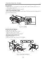
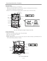
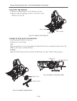
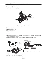
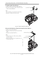
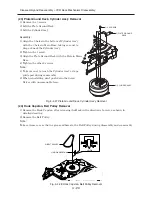
(8) Key P.C.B and VCR Main P.C.B
1) Remove screw [F].
2) Unplug the direct connector from VCR Main P.C.B, and then remove the Key P.C.B.
3) Disconnect the 2 FFCs.
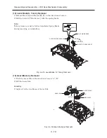
When reconnecting the FFCs, insert them into the connectors, following the instructions in
illustration, and check the connection status.
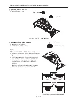
4) Remove 6 screws [F], and then remove the VCR Main P.C.B.
Fig. 4-2-8 Key P.C.B and VCR Main P.C.B
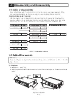
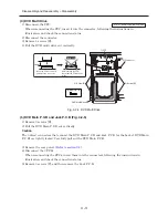
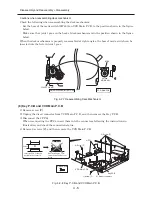
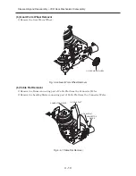
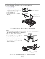
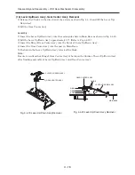
Cautions when reassembling deck mechanism
Check the following when reassembling the deck mechanism:
· Set the boss of the mode switch (SW603) on VCR Main P.C.B to the position shown in the figure
below.
· Make sure that joint 1 gear on the back of deck mechanism is in the position shown in the figure
below.
When the deck mechanism is properly reassembled at right angles, the boss of mode switch can be
inserted into the hole in joint 1 gear.
Fig. 4-2-7 Reassembling Deck Mechanism
Disassembly and Reassembly > Disassembly
SW603
BOSS
JOINT 1 GEAR
Deck mechanism-Bottom view
VCR Main PCB
MODE SW
After inserting the FFC,
check that the FFC doesn't
incline.
No Good
Parallel
Insert the FFC so that it is
parallel to the connector.
4) Screw [F]
4) Screw [F]
1) Screw [F]
3) FFC
2) Direct connector
Key P.C.B
VCR Main P.C.B
[F] M3X8(Gold)


