background image

3 - 3

Details of Servicing and Troubleshooting > Troubleshooting

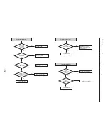
3-2 Troubleshooting

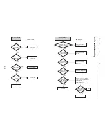
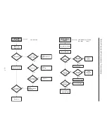
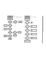
No Power Detected
(standby LED OFF)

F1S01 is normal?

D1S05~07, ZD1S01~2

SHORT and OPEN

are normal?

Check feedback IC1S02

Change short circuited or

opened parts

Change fuse

Check 2'nd Voltage

Replace Q1S01

NO

NO

Is there a voltage at

Collector of

Q1S01

NO

YES

YES

YES

Operation of

Q1S01 is

normal?

NO

YES

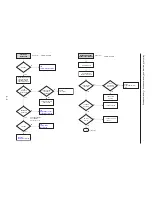
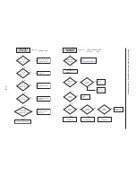
VCR Main PCB

Key Operation or

Remote Control Error

Is the measurement of

power within normal value?

End repairs

Check power circuit and
connector

Check the circuit around 
the clock

Check the circuit around 
IC601 reset

Check the soldering around 
IC601

Change  IC701

NO

NO

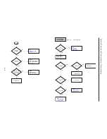
Key operations such

as STOP,PLAY,OPEN 

are normal?

Check the circuit around the switch.
check the condition of communication
with Main Micom
(IC601-4,6,14,15,16,RRQ,SRQ,SCLK,
DATA-IN,DATA-OUT)

NO

YES

YES

Check the circuit

around IC601 reset?

Check the soldering

around IC601 good?

NO

YES

XT601 14.318MHz

oscillation is normal?

NO

YES

YES

STOP,PLAY,OPEN

Key operations are

normal?

YES

VCR Main PCB

Change  
IC601

NO

Summary of Contents for DV-RF7U

Page 1: ...ANUAL SPECIFICATIONS AND PARTS ARE SUBJECT TO CHANGE FOR IMPROVEMENT Digital Media Division Tokai DVD VIDEO RECORDER with VIDEO CASSETTE RECORDER 2004 July TK No 0417E DV RF7U DO NOT RESELL OR DIVERT IMPROPERLY ...

Page 2: ...older FL Cassette Ass y Removal 4 8 2 Lever FL Arm Ass y Removal 4 8 3 Lever FL Door Removal 4 9 4 Slider FL Drive Gear FL Cam Removal 4 9 5 Gear Worm Wheel Removal 4 10 6 Cable Flat Removal 4 10 7 Motor Loading Ass y Removal 4 11 8 Bracket Gear Gear Joint 2 1 Removal 4 11 9 Gear Loading Drive Slider Cam Lever Load S T Ass y Removal 4 12 10 Lever Pinch Drive Lever Tension Drive Removal 4 13 11 Lev...

Page 3: ...ematic Wiring Diagrams S 1 S 1 Wiring Diagram S 1 S 2 S M P S Schematic Diagram S 2 S 3 Power Schematic Diagram S 3 S 4 Logic Schematic Diagram S 4 S 5 A V Schematic Diagram S 5 S 6 Hi Fi MTS Schematic Diagram S 6 S 7 MUX TM A V Input Schematic Diagram S 7 S 8 MUX Connector Schematic Diagram S 8 S 9 Audio Out Schematic Diagram S 9 S 10 Video Out Schematic Diagram S 10 S 11 Front Key Schematic Diag...

Page 4: ... are issued from time to time For the latest information always consult the current HITACHI Service Manual A subscription to or additional copies for HITACHI Service Manual may be obtained at a nominal charge from HITACHI SALES CORPORATION PRODUCT SAFETY NOTICE CAUTION There is a high voltage section inside the DVD recorder When repairing or inspecting it take great care to prevent electric shock ...

Page 5: ...observe the following cautions 1 Do not subject optical pickups to any severe vibrations or impact during movement installation or disassembly 2 When performing repair work do not perform disassembly any further than that described in this manual 3 Never turn the semi variable resistors for adjustment in optical pickup or DVD drive 4 NEVER look into the objective lens in optical pickup or directly...

Page 6: ...em note the regular indications in tables below Resistors Capacitors Coils Indication in list Regular indication KOHM k UF µF PF pF UH µH MH mH Parts Resistor Capacitor Coil Item Value Tolerance Power capacitance Indication No indication K k M M No indication 5 All tolerances other than 5 are indicated in schematic diagrams No indication 1 8W 1 16 W for leadless resistors with no indication All ca...

Page 7: ...ice method Basically components are replaced when servicing the DV RF7U However the service method is different for high density packaging PCBs and precision components Refer to the following table and perform the designated appropriate servicing Any changes that occur in the service method will be published using service bulletin etc Do not perform any servicing other than that described in this ...

Page 8: ...t Recording onto the disc may become impossible if optimizing is carried out too many times Playback may be impossible in some cases due to the recording condition This unit can play back DVD R discs recorded and finalized with a DVD video recorder It may not be able to play some DVD R discs depending on the disc and the recording condition DVD RW Disc Playback and Recording Recording and playback...

Page 9: ...rtridges are able to eject the disc inside Even if you are able to eject the disc always use the disc with the cartridge to ensure correct operation DVD RAM discs have a Write Protect tab in order to avoid accidental erasure of recorded data With the Write Protect tab set to PROTECT you can play the disc but recording or erasing will not work Set the Write Protect tab to UNPROTECT to format the di...

Page 10: ...e Lower quality about 6 hours 4 Copying digital camcorder content using DV input jack Record digital camcorder images onto DVD RAM DVD RW DVD R discs using the DV input jack IEEE 1394 4pin 5 Time Slip and Picture In Picture PIP Use the Time Slip function to play back the recorded images while a recording is proceeding DVD RAM only Use the PIP function to view the playback and recording screens at ...

Page 11: ...VHF 2 13 UHF 14 69 Cable TV broadcasting 1 125 Audio Audio input jacks 1 2 Optical Coaxial digital audio output Output Video Video input jacks 1 2 S Video output 1 Y 1 0 Vp p C 0 286 Vp p at 75 Component output Y 1 0 Vp p Pb 0 70 Vp p Pr 0 70 Vp p at 75 Picture Compression format MPEG II Audio Compression format Dolby AC 3 256 kbps DVD Recording time Max 6 hour using 4 7 GB disc XP 60 min SP 120 m...

Page 12: ...discs 12 cm 5 4 7 GB DVD RW discs Ver 1 1 Ver 1 1 with CPRM 12 cm 5 4 7 GB DVD R discs 8 cm 3 1 4 GB DVD R discs for General Ver 2 0 DVD VIDEO discs CD Audio discs CD DA CD R CD RW discs CD DA MP3 formatted discs VHS S VHS SQPB DV RMRF7U 1 Front 1 Front 2 Front 1 Rear 1 1 Rear 1 Rear 1 Rear 2 Rear 2 Optical 1 Coaxial 1 Yes Front DV RX5000U 430 W x 283 D x 79 H mm Approx 26 W Standby power Approx 3...

Page 13: ... Motion Play Position Memory Disk Manager Edit Title List Edit Playlist Divide Program Digital Recording DV to VCR Dubbing DVD to VCR Playlist dubbing DVD to VCR One Touch Recording OTR Picture Search Jet Search S VHS Playback Go To 0 00 00 Stop End Search Forward Intro Scan Reverse Intro Scan DV RF7U Yes Yes Yes Yes Yes Yes Yes Yes Yes 30 seconds Yes Yes Yes Yes Yes Yes Yes Yes Yes Yes Yes Yes Ye...

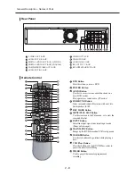
Page 14: ...DVD is activated DVD RAM is activated DVD R or DVD RW is activated Progressive Scan mode is working When you watch SAP STEREO channel or playback Hi Fi VCR tapes STEREO indica tor lights VCR is activated DVD or CD media is loaded Record function is working The time counter position or current deck status is indicated When you set a Timer recording or current deck status is indicated this indicator...

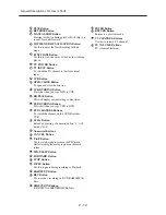
Page 15: ...IO Button Use this to access various audio functions on a disc DVD mode This operates as sound mute TV mode SURROUND Button Gives surround sound effect even with only two front speakers L R REC MODE Button MENU PLAY LIST Button Use this to return to the Title menu or to view the recorded files list INPUT Button Select line input signal in external input mode Tuner or Line input MAIN MENU Button Br...

Page 16: ...pen and close the disc tray VCR DUBBING Button Press this when you copy DVD to VCR DISPLAY Button This will display current setting or disc status DVD DUBBING Button Press this when you copy VCR to DVD DVD CHANNEL Buttons To switch the channel on this DVD Recorder VCR 1 100 Button Extended pressing of numeric button 1 will deliver 100 Numerical Buttons CANCEL Button P in P Button Use to watch a su...

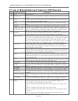
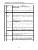
Page 17: ... Dolby Laboratories in U S also simply referred as AC3 format Supports 5 channel full range sound and one channel for sub woofer sound playback Dynamic Range Control Adjusting the audio range of maximum and minimum levels dynamic range will improve audio signal when for example dialog is hard to hear or user is watching movies late at night Digital Theater System Sound system as for movie theaters...

Page 18: ...9 images on 4 3 screens with black bands across the top and bottom of screen One format to play Video CD User can select desired screens and data while watching the displayed menu screen This function converts interlaced images to non interlaced images and displays them It can play back 24 frame second images included in DVD movie software etc The video signal is separated into chrominance C and l...

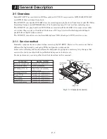
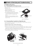
Page 19: ... to damage the disc Fig 3 1 1 Removing Disc B A SLIDER CAM SCREWDRIVER TRAY DISC 3 1 2 Removing Video Cassette from Faulty Recorder If video cassette cannot be removed due to fault disassemble the recorder and remove the video cassette by the following procedure 1 Remove the top cover See 4 2 1 for removal procedure 2 Remove the front panel See 4 2 2 for removal procedure 3 Remove the setscrew and...

Page 20: ...sc into the tray Recognition of the disc will start and the screen for confirming updating will appear 3 Choose Yes and then press the ENTER button on remote control 4 When updating is complete the tray will automatically open Remove the disc 5 Turn the recorder off and then on again The tray will close 6 Hold down the CH UP CH DOWN buttons on recorder simultaneously for approx 5 seconds to displa...

Page 21: ...Error Is the measurement of power within normal value End repairs Check power circuit and connector Check the circuit around the clock Check the circuit around IC601 reset Check the soldering around IC601 Change IC701 NO NO Key operations such as STOP PLAY OPEN are normal Check the circuit around the switch check the condition of communication with Main Micom IC601 4 6 14 15 16 RRQ SRQ SCLK DATA I...

Page 22: ... AND PATTERN CHECK IC601 XT601 SEE VIDEO MISSING IN EE MODE NO NO NO YES NO PB VIDEO SEE VIDEO MISSING IN PLAY MODE NO YES YES YES DOES NOT OPERATE OR OPERATES BUT STOPS SOON YES VCR Section VCR Main PCB LOAD A TAPE AND PRESS PLAY BUTTON TURN POWER ON MECHANISM DOESN T OPERATE IN PLAY MODE TAPE LOADING OPERATION LOAD IC601 59 HIGH IC601 60 LOW CYLINDER ROTATION SW 30Hz IC601 23 CHECK CYL FG PG IC6...

Page 23: ...UPPLY REEL SENSOR PT601 PT602 SEE CAPSTAN DOES NOT ROTATE NO DC YES YES PULSE NO A RECORD MODE DOESN T OPERATE PLAY OPERATION LOAD VCR WITH A BLANK TAPE AND PRESS RECORD BUTTON REC MODE SAFETY TAB D REC A H IC601 30 SEE AUDIO MISSING IN RECORD MODE CHANGE SW602 CHECK IC601 CHANGE TAPE SEE PLAY MODE INOPERATIVE EJECT NO NO YES NO REC VIDEO SEE VIDEO MISSING IN RECORD MODE NO YES YES YES YES VCR Sec...

Page 24: ... CHECK CN604 5 9 3 2V CHECK IC601 CHECK POWER BLOCK YES YES YES CHECK MECHANISM NO IC601 67 FG pulse CHECK CAPSTAN MOTOR YES VCR Section VCR Main PCB FWD SEARCH DOESN T OPERATE PLAY OPERATION PRESS F FWD FOR FORWARD SEARCH CHECK IC601 CHECK CAPSTAN MOTOR IS CAPSTAN SPEED CHANGED SEARCH OPERATION NOISE BAR LOCKING END ADJUST ACE HEAD CHANGE DECK CHANGE IC601 SEE PLAY MODE INOPERATIVE NO NO NO YES N...

Page 25: ...C601 58 HIGH 5V IC601 59 HIGH 5V IC601 58 LOW 0V CHECK CASSETTE LOADING MECHANISM YES YES NO CN604 8 12V YES NO YES VCR Section VCR Main PCB PLACE VCR IN STOP MODE CHANGE IC301 LINE 2 VIDEO INPUT VIDEO MISSING IN EE MODE IC301 26 VIDEO OUT NO NO NO IC601 49 VIDEO IN YES YES Q801 E VIDEO OUT YES CHECK IC601 NO IC301 53 54 VIDEO DATA CLOCK YES CHECK OSD PICTURE CHECK IC801 Q801 CHECK LINE OUT and C8...
Page 26: ...8 Power 5V and R320 NO YES IC301 73 SP IC301 66 SLP CHECK REC FM signal CHECK drum wafer and VIDEO head NO YES VCR Section VCR Main PCB VIDEO MISSING IN PLAY MODE VIDEO EE MODE OPERATION PLACE THE VCR IN PLAY MODE CHANGE IC301 CHECK IC601 CHECK VIDEO HEAD CHECK C305 CHECK IC601 23 CHECK VIDEO OUT LINE SEE VIDEO MISSING IN EE MODE NO YES YES NO YES YES VIDEO FM IC301 14 VIDEO IC301 22 VIDEO IC301 2...

Page 27: ... IC301 CHECK THE REC LINE SEE VIDEO MISSING IN RECORD MODE NO NO NO YES YES CHECK XT301 CHANGE XT301 NO CHANGE IC301 YES YES VCR Main PCB COLOR MISSING IN PLAY MODE FM ENV IC301 14 COLOR MONITOR IC301 46 COLOR KILLER IC301 60 2V SW 30Hz IC301 57 CHANGE IC301 CHECK IC301 48 51 XT301 CHECK IC601 SEE VIDEO MISSING IN PLAY MODE NO NO NO NO YES YES YES NOTE XT301 Always 3 579545MHz VCR Section VCR Main...

Page 28: ...al out CHANGE IC601 CHECK C618 C619 CHECK C626 R639 YES NO YES NO VCR Section VCR Main PCB SELECT LINE MODE WITHOUT INPUT SIGNAL BLUE MISSING IN STOP MODE CHANGE IC601 CHECK IC601 37 38 14 318MHz out CHECK IC601 52 53 AFC signal CHECK C626 R639 CHECK C618 C619 NO NO YES YES CHECK IC601 50 SYNK signal CHECK C622 R638 NO YES VCR Section VCR Main PCB ...

Page 29: ...GNAL NO YES IC801 42 54 AUDIO SIGNAL CHANGE IC501 CHECK Q303 YES IC501 51 3 58MHz CHECK CLK DATA IC501 37 38 IC501 57 AUDIO SIGNAL INPUT NO VCR Section VCR Main PCB Jack PCB 5xx 6xx 4xx 8xx MISSING AUDIO IC501 78 80 AUDIO SIGNAL IC501 26 AUDIO FM CHECK CYLINDER CHANGE IC501 CHECK C511 R506 CHANGE IC501 CHECK AUDIO MISSING IN EE MODE AUDIO MISSING IN RECORD MODE MONO HIFI MONO NO NO YES YES IC501 9...

Page 30: ...301 10 AUDIO SIGNAL IC301 9 AUDIO FM SIGNAL IC301 7 MIX SIGNAL AUDIO 70KHz Q305 OSCILLATION CHECK AUDIO MISSING IN PLAY MODE CHECK ACE HEAD MONO NO CHECK AUDIO MISSING IN EE MODE PLACE THE VCR IN PB MODE CHANGE IC501 AUDIO MISSING IN PLAY MODE CHECK C349 R333 or CHANG IC301 CHECK ACE HEAD C353 C348 R332 AND CHANGE IC301 AUDIO SELECT IC501 24 27 AUDIO FM MIXED CHECK IC501 39 A H D SW CHANGE CYLINDE...

Page 31: ...O NO NO YES YES YES VCR Section VCR Main PCB CAPSTAN DOES NOT ROTATE PLACE THE VCR IN PLAY MODE CN604 2 15V CN604 3 PC 5V CN604 5 3 2V CN604 9 2 6V IC601 33 OUTPUT PWM IC601 35 OUTPUT PWM CHECK CAPSTAN MOTOR CHECK R615 C606 R630 CHECK R632 CHANGE IC601 CHECK IC601 CHECK AL15V LINE IN THE POWER BLOCK CHECK PC5V LINE IN THE POWER BLOCK NO NO NO NO YES NO YES NO YES YES YES YES VCR Section VCR Main P...

Page 32: ...ubleshooting DRUM DOES NOT ROTATE CN604 8 12V CN604 3 5V CN604 12 2 5V CHECK CYLINDER MOTOR CN601 34 PWM OUT CHECK 5V LINE CHECK PC12V LINE IN THE POWER BLOCK NO NO NO YES YES YES CHANGE IC601 NO CHECK R631 R617 R618 C609 C610 VCR Section VCR Main PCB ...

Page 33: ...o Check the connection between MCON1 and CN02 Yes Yes Yes Tray repeats open close operation Is the 40 pin FFC cable between main deck inserted correctly Change the main board No Reinsert FFC cable correctly Yes Disc loading error Voltage of AR17 and AR31 is lower than 0 6V Jack PCB Proper vcc of AIC4 Jack PCB Check the passive components around jack pin Check mute block No No Check A12VCC line Out...

Page 34: ...ut to pin 13 of DOIC1 No No Proper signal output from pin 6 of DOIC1 Replace DOIC1 Yes Yes Yes Skip setting check hardware problem No digital audio out Replace Main PCB Check select signal at pins 44 46 56 58 of IC801 Jack PCB Check pin62 of IC801 pin18 of MCON2 and pin16 of MCON2 on Jack PCB Check passive components around jack pin and IC801 Check pin63 64 input select of IC801 No No Check SMPS c...

Page 35: ...Yes No Video signal of about 1V appears at output jack Check the connection between VIC1 and output jack Yes VIDEO output error CN3 10 8 on jack PCB has normal level Check the RCA cable No No Check Main PCB Analog signals are input normaly VIC1 Jack PCB No No No Check the connection between CN2 10 8 on Main PCB and VIC1 Power is normal at VIC1 1 24 34 5V VIC1 13 is in high state Check the connecti...

Page 36: ...VIC1 and power Video signals of about 1V appear at output jack Check the connection between VIC1 and output jack Yes Yes Yes Yes Component output error Check the RCA cable No Yes Progressive output error Is there P480 Mark on FLT After DVDR is in stop state push the progressive scan key on the Front panel IC801 4 has nomal level Jack PCB IC801 21 has nomal level Change Main PCB Check the connectio...

Page 37: ...21 has nomal level Change Main PCB Check the connection between IC801 6 and L2 pin jack No No IC801 62 55 of input power Yes Yes Line2 Video Input Error CN3 15 17 have nomal level Jack PCB Change Main PCB Check the connection between CN3 15 17 and L2 S video jack No Yes Line2 S Video Video Input Error ...

Page 38: ...the components on all the routes 4 Fig 4 1 1 Disassembly Flowchart 4 2 Cabinet Disassembly Information Numbers in figures are step numbers in disassembly procedure and letters in brackets show the types of screw 1 Top Cover 1 Remove the 7 screws A 2 Slightly open both ends on the front side of top cover and lift the top cover in the direction of the arrow Fig 4 2 1 Top cover Key P C B 4 2 8 Front ...

Page 39: ...sitioned outside the door Fig 4 2 2 Front Panel 3 Rear Panel and FAN Motor 1 Disconnect the power cable 2 Remove 4 screws B and the screw G 3 Disconnect the fan motor connector 4 Release the 2 tabs and remove the rear panel When disassembling only FAN motor a Remove 2 screws C b Disconnect the fan motor connector 3 in the figure Fig 4 2 3 Rear Panel and FAN Motor 1 Tab A 1 Tab B Front Panel Casset...

Page 40: ...ors following the instructions in illustration and check the connection status 5 Remove 3 screws F and then remove the Jack P C B Fig 4 2 4 DVD Multi Drive 4 DVD Multi Drive 1 Disconnect the FFC FFC Flexible flat cable When reconnecting the FFC insert it into the connector following the instructions in illustration and check the connection status 2 Disconnect the connector 3 Remove 4 screws D 4 Pu...

Page 41: ... the ACE head connector 3 Remove 4 screws E 4 While unplugging the 3 direct connectors that connect the deck mechanism and VCR Main P C B lift the entire deck mechanism vertically Fig 4 2 6 Deck Mechanism 4 FFC a FFC 5 Screw F 5 Screw F b Screw F 1 Screw D 1 Screw D Direct Connector Front P C B Jack P C B DVD Main P C B 5 Screw F D M3X12 Gold F M3X8 Gold 3 Rear Panel Parallel Insert the FFC so tha...

Page 42: ...s of the mode switch SW603 on VCR Main P C B to the position shown in the figure below Make sure that joint 1 gear on the back of deck mechanism is in the position shown in the figure below When the deck mechanism is properly reassembled at right angles the boss of mode switch can be inserted into the hole in joint 1 gear Fig 4 2 7 Reassembling Deck Mechanism Disassembly and Reassembly Disassembly...

Page 43: ...ARM ASS Y 4 HOLDER FL CASSETTE ASS Y 5 LEVER FL DOOR 6 SLIDER FL DRIVE 1 2 3 4 5 6 Fig 4 3 2 Top View of Parts Locations 2 1 FE HEAD 2 CYLINDER ASS Y 3 ACE HEAD ASS Y 4 LEVER UNIT PINCH ASS Y 5 LEVER 9 GUIDE ASS Y 6 LEVER TENSION ASS Y 7 BAND BRAKE ASS Y 8 DISK S REEL 9 LEVER S BRAKE ASS Y 10 GEAR IDLE 11 LEVER IDLE 12 LEVER T BRAKE ASS Y 13 DISK T REEL 1 2 3 4 5 6 7 8 9 10 11 10 12 13 ...

Page 44: ...ig 4 3 3 Bottom View of Parts Locations 1 GEAR JOINT 1 2 GEAR JOINT 2 3 BRACKET GEAR 4 MOTOR CAPSTAN ASS Y 5 LEVER T LOAD ASS Y 6 GEAR LOADING DRIVE 7 LEVER S LOAD ASS Y 8 HOLDER CLUTCH ASS Y 9 BELT PULLEY 10 SLIDER CAM 1 2 3 4 5 6 7 8 9 10 4 3 2 Bottom View ...

Page 45: ... this time You have to hold the Lever FL Cassette R continuously until the Holder FL Cassette Ass y is removed completely Note Be sure to insert Lever FL Cassette R in the direction of A to prevent separation and breakage of the Lever FL Cassette R during disassembly and reassembly 4 4 VCR Deck Mechanism Disassembly A RAIL B BOSS A LEVER FL CASSETTE R HOLDER FL CASSETTE ASS Y Fig 4 4 2 Lever FL Ar...

Page 46: ...r FL Door in the direction of arrow B Fig 4 4 4 Slider FL Drive Removal 4 Slider FL Drive Gear FL Cam Removal 1 Pull the Slider FL Drive to the front 2 Remove the Gear FL cam Note When reinstalling be sure to reassemble the Slider FL Drive after inserting the Boss of Lever FL ARM into the Groove in Slider FL Drive Assembly Align the Gear FL Cam with the Gear Worm Wheel Post as shown Refer to Timin...

Page 47: ...k Mechanism Disassembly Fig 4 4 6 Gear Worm Wheel Removal 5 Gear Worm Wheel Removal 1 Remove the Gear Worm Wheel Fig 4 4 7 Cable Flat Removal 6 Cable Flat Removal 1 Remove the Drum connecting part of Cable Flat from the Connector Wafer 2 Remove the Loading Motor connecting part of Cable Flat from the Connector Wafer ...

Page 48: ...cket Gear Gear Joints 1 2 Removal 8 Bracket Gear Gear Joints 2 1 Removal 1 Remove the screw 2 Remove the Bracket Gear 3 Remove Gear Joint 2 4 Remove Gear Joint 1 Assembly 1 Be sure to align the dot mark of Gear Joint 1 with the dot mark of Gear Joint 2 as shown in Fig 4 4 10 Refer to Timing Point 1 2 Confirm Timing Point 2 of Gear Joint 2 and Slider Cam Refer to Timing Point 2 Fig 4 4 10 Gear Join...

Page 49: ...ve Slider Cam Lever Load S T Ass y Assembly Assembly 1 When reinstalling be sure to align the dot of Lever Load T Ass y with the dot of Lever Load S Ass y as shown in the drawing Refer to Timing Point 1 2 Insert Pins A B C D into the holes in Slider Cam 3 Be sure to align the dot of Lever Load T and the dot of Gear Loading Drive Refer to Timing Point 2 4 Align the dot of Gear Loading drive with th...

Page 50: ... 14 Lever Tension Ass y Band Brake Ass y Removal 11 Lever Tension Ass y Band Brake Ass y Removal 1 Remove the Lever Brake S Ass y Refer to Fig 4 4 15 2 Remove the Spring Tension Lever 3 Rotate the stopper of Main Base in the direction of arrow A 4 Lift the Lever Tension Ass y and Band Brake Ass y Note 1 When replacing the Lever Tension Ass y be sure to apply Grease on the post 2 Take care not to t...

Page 51: ... the spring brake Note Take extreme care not to fold or transform Spring Brake during removing or reinstalling 13 Gear Idle Ass y Removal 1 Push the Lever Idle in the direction of arrow A B 2 Lift the Lever Idle Assembly 1 Apply oil to the two Bosses of Lever Idle 1 HOOK A 2 LEVER S BRAKE ASS Y 2 LEVER T BRAKE ASS Y 2 SPRING BRAKE 1 HOOK B 1 HOOK C Fig 4 4 16 Gear Idle Ass y Removal A B GEAR IDLE ...

Page 52: ... Removal 15 Holder Clutch Ass y Removal 1 Remove the Washer Slit 2 Lift the Holder Clutch Ass y Note When you reinstall the Holder Clutch Ass y 1 Check the condition of spring as shown in detail A 2 Don t push the Holder Clutch Ass y down with excessive force Just insert Holder Clutch Ass y into post center with dead force and Rotate it smoothly Be sure to confirm that the spring is in the slit of...

Page 53: ...lar hole in Main Base as shown in Fig 4 4 20 2 Lift the Lever Up Down Ass y approximately 35 Refer to Fig 4 4 20 3 Insert the Ring of Gear Center Ass y into the Guide of Lever Up Down Ass y 4 Insert the Gear Center Ass y into the post on Main Base 5 Push down the Lever Up Down Ass y to lock of the Hook Note Be sure to confirm that Ring of Gear Center Ass y is between the Guides of Lever Up Down As...

Page 54: ...the Guide Cassette Door making sure the Hook A locks in place Fig 4 4 22 Lever Unit Pinch Ass y Plate Joint Spring Pinch Drive Removal 18 Lever Unit Pinch Ass y Plate Joint Spring Pinch Drive Removal 1 Lift the Lever Unit Pinch Ass y 2 Remove the Plate Joint from Lever Unit Pinch Ass y 3 Remove the Spring Pinch Drive Note 1 Take extreme care so that no grease adheres the Roller Pinch 2 When reinst...

Page 55: ... Remove the Spring 9 Guide 2 Lift the Lever 9 Guide Ass y in the direction of arrow A and B Note 1 Take extreme care so that no grease adheres to the tape Guide Post 2 After reinstalling make sure the bottom of Post 9 Guide faces the top side of Main Base 1 2 FE HEAD Fig 4 4 24 FE Head Removal 20 FE Head Removal 1 Rotate the FE head in the direction of arrow 2 Lift the FE Head ...

Page 56: ...Head Removal 21 ACE Head Removal 1 Pull out the FPC from the connector of ACE Head Ass y 2 Remove the screw 3 Lift the ACE Head Ass y 1 SLIDER S ASS Y 1 SLIDER T ASS Y Fig 4 4 26 Slider S T Ass y Removal 22 Slider S T Ass y Removal 1 Move the Slider S T Ass y in the slots and then lift them to remove Refer to arrow ...

Page 57: ...Ass y 2 Tighten the 1 screw 3 Align the Plate Ground Deck with the Hole in Main Base 4 Tighten the other 2 screws Note 1 Take care not to touch the Cylinder Ass y or tape guide post during reassembly 2 When reinstalling don t push down the Screw Driver with unreasonable force HOOK 1 HOOK CAPSTAN 2 BELT PULLEY Fig 4 4 28 Hook Capstan Belt Pulley Removal 24 Hook Capstan Belt Pulley Removal 1 Remove ...

Page 58: ...he 3 holes in Main Base Be careful not to drop or knock the Motor Capstan Ass y 2 Tighten the 3 screws in the order shown in detailed drawing 3 Assemble the Hook Capstan Note After tightening the screws check if there is a gap between the screw heads and the top side of Main Base There must be no gap between them After reinstalling adjust the tape transport system again A B C 3 MOTOR CAPSTAN ASS Y...

Page 59: ...B B B C C C C C C C C C C C C C C C C C C C C A A A A A B B B B B B B B B B B B A B B B B B B B B B B B B B B B B B B B B B B B B B B B B B B B B B B B B B B B B B B B B B B B B B B B B B B Periodic time of applying oil Apply oil after cleaning The excessive applying oil may be the cause of malfunction To clean the parts use patch and alcohol solvent After cleaning use the video tape after alcohol...

Page 60: ...t specified 1 Connect a color bar generator to the video input 1 jack 2 Connect a monitor TV to the video output 1 jack 3 Connect a monitor TV able to handle a stereo signal to the audio output 1 jack 3 Cautions on adjustment 1 The following conditions apply when otherwise not specified probe of oscilloscope 10 1 Synchronization of oscilloscope Internal sync 2 When performing more than one adjustm...

Page 61: ...f the corresponding adjustment button is pressed while TEST is being displayed the adjustment will be performed automatically When adjustment is finished turn power off to release the adjustment mode 1 Locations of reference buttons on remote control Fig 5 2 1 Location of reference button of remote control 2 TEST location for adjustment mode setting Fig 5 2 2 Locations of Test points Tracking Cent...

Page 62: ...ustment mode 5 2 3 NVRAM Option Setting 1 NVRAM Option has been adjusted at the factory 2 If the VCR Main P C B Micom IC601 and NVRAM IC603 EEPROM are replaced be sure to set the corresponding option number of the required model If the option is not set the unit will not operate Turn the recorder on with no disc or tape inserted and then perform the following operations after the loading display d...

Page 63: ...for transport adjustment To maintain the height of the guide post and prevent damage do not apply excessive force to the main base Fig 5 3 1 Locations of Tape Transport Components Fig 5 3 2 Tape Running CYLINDER ASS Y TAKE UP REEL DISK 8 GUIDE POST SUPPLY REEL DISK CAPSTAN PINCH ROLLER SUPPLY GUIDE ROLLER HEIGHT ADJUST FULL ERASE HEAD 3 GUIDE POST TENSION POST TAKE UP GUIDE ROLLER HEIGHT ADJUST 9 ...

Page 64: ...See Fig 5 3 1 and Fig 5 3 2 If the tape wrinkle is still observed at the 8 guide post perform the ACE head tilt adjustment 1 ACE Head Assembly Adjustment a ACE Head Height Adjustment 1 Play back the alignment tape 2 Observe the surface of audio head using a dental mirror 3 Turn screw C clockwise or counterclockwise until the gap between the lower tape edge and the lower edge of control head is app...

Page 65: ... B 3 If a curl or wrinkle of the tape occurs slightly turn tilt adjustment screw A on the ACE head ass y See Fig 5 3 3 4 Reconfirm the ACE head height See section a ACE Head Height Adjustment c Audio Azimuth Adjustment 1 Load alignment tape Mono scope and play back the 7 kHz signal 2 Connect channel 1 scope probe to the audio output 3 Adjust screw B to maximize the audio level See Fig 5 3 3 Fig 5 ...

Page 66: ...obe to TP3 ENVELOPE and CH 2 probe to TP4 Head S W Trigger and then trigger the oscilloscope from CH 2 5 Slightly loosen the X value securing screw do not excessively loosen See Fig 5 3 3 6 Insert a flat bladed screwdriver into the groove for X value adjustment and then adjust the X value to maximize the CH 1 FM output 7 Tighten the X value securing screw 8 Turn power off to release the adjustment...

Page 67: ...satisfied perform the following adjustments a Maximum output of FM envelope b Minimum output of FM envelope at the entrance side c Minimum output of FM envelope at the center point d Maximum output of FM envelope at the exit side 4 If there is a drop in amplitude of FM envelope on the entrance side adjust the supply guide roller 5 If there is a drop in amplitude of FM envelope on the exit side adj...

Page 68: ...of envelope rises within 3 seconds Fig 5 3 9 Rise of FM Envelope when Operation Mode Changes from RPS to Play 4 Envelope Check 1 Use T 120 E 120 tape to perform recording and playback on the same machine 2 Check the FM envelope waveform and make sure that amplitudes A and B are equal If this cannot be confirmed check the cylinder and replace it if necessary Fig 5 3 10 FM Envelope Input and Output ...

Page 69: ...on of gear center ass y 3 Brake is operated by slider cam in FF REW mode 4 The accurate driving force is transmitted by gears Gear Center Ass y Note Note Note Note Note If the following specifications are not satisfied replace the holder clutch ass y and then recheck MODE Play RPS REV Picture Search GAUGE Cassette Torquemeter Cassette Torquemeter TORQUE 4 12 1 1 mN m 42 11 g cm 14 22 2 9 mN m 145 ...

Page 70: ...ervice parts as of the date of issue of this manual 003 Jack PCB Component replacement 004 VCR Main PCB Component replacement 005 Front PCB Component replacement 006 Key PCB Component replacement 001 DVD Multi drive Unit replacement 104 002 DVD Main PCB Circuit board assembly replacement 102 101 103 107 Cylinder 106 105 W004 W004 905 905 904 904 904 904 904 904 904 W001 W001 903 903 903 ...

Page 71: ...ism Section Top view 107 T015 T014 T003 W201 T004 T005 T033 W015 T011 T012 T022 T021 T019 T023 T024 T028 T026 T020 T027 T002 T029 T007 T025 T032 T030 T013 T008 T009 T031 W016 T010 T016 W015 GREASE TS 100G Goandong OIL EP 56 Mitsubishi T005 Rear side Grease point ...

Page 72: ...eck Mechanism Section Bottom view T046 T044 T041 T042 T043 T034 T035 T037 T038 T049 T047 T050 T048 T040 T036 T039 T045 T006 GREASE TS 100G Goandong OIL EP 56 Mitsubishi T035 Rear side Grease point T041 Rear side Grease point T043 Rear side Grease point ...

Page 73: ...BAND BRAKE T026 TJ18096 LEVER BRAKE S T027 TJ18097 LEVER BRAKE T T028 TJ18098 SPRING T029 TJ18099 SLIDER FL T030 TJ18101 HOLDER FL T031 TJ18102 SPRING T032 TJ18103 LEVER FL ARM T033 TJ18104 GUIDE CASS T034 TJ18114 GEAR JOINT T035 TJ18115 GEAR JOINT T036 TJ18107 BRACKET GEAR T037 TJ18113 SLIDER CAM T038 TJ18112 LEVER PINCH T039 TJ18119 HOOK CAPSTAN T040 TJ18111 LEVER TENSION T041 TJ18116 GEAR LOADI...

Page 74: ... DIODE 1N4148 6 2 2 Electrical Parts List P NO DESCRIPTION SYMBOL NO P NO DESCRIPTION SYMBOL NO D704 TJ18344 DIODE 1N4148 DOIC1 TJ18143 IC M74HCU04 DOL1 TJ18358 FILTER DOL3 TJ18256 INDUCTOR 10UH DOZ1 TJ18357 ZENER DIODE UDZ9 1B DOZ2 TJ18357 ZENER DIODE UDZ9 1B DT701 TJ18323 LED DISPLAY F1S01 TJ18189 FUSE 250V 1 6A FC1S01 TJ18221 FUSE FC1S02 TJ18221 FUSE FJACK1 TJ18337 CONNECTOR 27P FJACK2 TJ18337 ...

Page 75: ... TJ18353 SWITCH TACT SW704 TJ18353 SWITCH TACT SW705 TJ18353 SWITCH TACT SW706 TJ18353 SWITCH TACT SW709 TJ18353 SWITCH TACT SW710 TJ18353 SWITCH TACT SW712 TJ18353 SWITCH TACT SW713 TJ18353 SWITCH TACT SW714 TJ18353 SWITCH TACT SW715 TJ18353 SWITCH TACT SW721 TJ18353 SWITCH TACT SW722 TJ18353 SWITCH TACT TM401 TJ18299 TUNER BLOCK VIC1 TJ18362 IC LA73054 VL6 TJ18256 INDUCTOR 10UH VZ1 TJ18357 ZENER...

Page 76: ...rdering The correct part number is shown in the parts list may be slightly different or amended since this drawing was prepared Important safety notices Components identified with the mark have the special characteristics for safety When replacing any of these components Use only the same type 1 2 3 4 5 6 7 8 9 10 11 12 13 14 15 16 17 18 19 20 21 22 23 24 25 26 27 33 32 31 30 29 28 27 26 25 24 23 ...

Page 77: ...4 3 2 1 A B C D E F A B C D E F 8 7 6 5 4 3 2 1 8 7 6 5 S 2 S 2 S M P S Schematic Diagram VCR Main P C B 0 01 630V 220P 1KV 100nF To POWER 0 01 P Parts with Heat Sink ...

Page 78: ... 3 Power Schematic Diagram VCR Main P C B From S M P S 1 2 3 4 To DECK MECHANISM 3PL To Logic To MUX Connector Jack P C B MCON2 To FAN MOTOR 2PL 1AP 10HL 9HL 3HT 2HT 2AP AL5V 1PL L M PC9V PC5V PC5V From Logic From To Hi Fi MTS To A V To A V Hi Fi MTS Logic 1N5408 ...

Page 79: ...P C B 0 01 0 01 0 022 0 047 1 330P 0 01 0 01 0 01 0 01 To CAPSTAN MOTOR Key P C B 0 01 0 1 100P 1 0 01 0 1 0 01 0 01 0 0015 0 015 0 1 0 01 0 001 0 01 0 01 1PL 1HL 2HL 3HL 4HL 5HL 2PL 3PL 17 18 MTS To Power To MUX CONNECTOR JACK MCON1 1AL 2AL 3AL 4AL 5AL 6AL 7AL 8AL 9AL 11AL 12AL 13AL 14AL 15AL CN02 ...

Page 80: ... 6 5 S 5 S 5 A V Schematic Diagram VCR Main P C B To CYLINDER 0 01 0 01 0 01 0 01 1 0 0068 0 01 0 01 0 01 0 01 0 01 0 01 0 047 0 047 0 047 0 047 0 1 0 1 1 0 0022 0 01 0 0082 0 0082 560P 360P 180P 0 1 0 0022 0 1 1 0 1 470P 0 0018 0 015 0 01 1AP 2AP POWER ...

Page 81: ...4 3 2 1 A B C D E F A B C D E F 8 7 6 5 4 3 2 1 8 7 6 5 S 6 S 6 Hi Fi MTS Schematic Diagram VCR Main P C B 0 01 0 033 0 01 0 0047 0 1 0 1 0 01 0 01 0 01 0 01 0 1 0 0047 POWER ...

Page 82: ...ack P C B To MUX CONNECTOR To MUX CONNECTOR To MUX CONNECTOR To VIDEO OUT To VIDEO OUT To MUX CONNECTOR To MUX CONNECTOR To AUDIO OUT 0 1 0 1 0 1 0 1 0 1 0 1 0 1 0 01 330P 330P 0 1 330P 0 1 0 1 100P 330P LINE IN 1 LINE OUT To MUX CONNECTOR To VIDEO OUT To MUX CONNECTOR To FRONT KEY FRONT P C B FJACK2 ...

Page 83: ...Connector Schematic Diagram Jack P C B To POWER VCR MAIN CN01 To LOGIC VCR MAIN CN02 To DVD MAIN P C B To MUX TM A V INPUT To MUX TM A V INPUT To MUX TM A V INPUT To MUX TM A V INPUT To MUX TM A V INPUT To AUDIO OUT To AUDIO OUT To VIDEO OUT To VIDEO OUT 0 1 0 1 0 1 0 1 ...

Page 84: ... 5 4 3 2 1 8 7 6 5 S 9 S 9 Audio Out Schematic Diagram Jack P C B 220 220 To MUX CONNECTOR To MUX TM A V INPUT To MUX CONNECTOR To MUX CONNECTOR To DVD MAIN 0 1 220 220 0 0012 0 1 0 0012 150P 150P 0 1 0 1 0 1 0 1 220P 220P 0 1 0 1 0 1 0 1 ...

Page 85: ... 10 S 10 Video Out Schematic Diagram Jack P C B To MUX TM A V INPUT To MUX TM A V INPUT To MUX CONNECTOR To MUX CONNECTOR To DVD MAIN 0 1 0 1 0 1 0 1 0 1 0 1 0 1 0 1 220P 220P 220P 220P 220P 220P 220P 220 220 220 220 220 220 220 220 220P DV RV7000 Japan only ...

Page 86: ...4 3 2 1 A B C D E F A B C D E F 8 7 6 5 4 3 2 1 8 7 6 5 S 11 S 11 Front Key Schematic Diagram Front P C B To MUX TM A V INPUT JACK P C B DV JACK AVIO PROGRE SSIVE DISK OPEN CLOSE POWER CH CH ...

Page 87: ...4 3 2 1 A B C D E F A B C D E F 8 7 6 5 4 3 2 1 8 7 6 5 C 1 C CIRCUIT BOARD DIAGRAMS C 1 VCR Main P C B COMPONENT SIDE ...

Page 88: ...4 3 2 1 A B C D E F A B C D E F 8 7 6 5 4 3 2 1 8 7 6 5 C 2 CONDUCTOR SIDE ...

Page 89: ...4 3 2 1 A B C D E F A B C D E F 8 7 6 5 4 3 2 1 8 7 6 5 C 3 C 2 Jack P C B COMPONENT SIDE ...

Page 90: ...4 3 2 1 A B C D E F A B C D E F 8 7 6 5 4 3 2 1 8 7 6 5 C 4 CONDUCTOR SIDE ...

Page 91: ...4 3 2 1 A B C D E F A B C D E F 8 7 6 5 4 3 2 1 8 7 6 5 C 5 C 3 Front P C B C 4 Key P C B COMPONENT SIDE COMPONENT SIDE CONDUCTOR SIDE CONDUCTOR SIDE ...

Page 92: ...o D A PCM1753 IEEE1394PHY TSB41AB1 TM BLOCK TM401 TIC1 IC801 AIC9 IC601 DIC1 VIC1 AIC1 IC301 IC501 PIC1 ATAPI VCR DECK X 11 RF RF Out VHF UHF S VIDEO LINE1 LINE2 CVBS from Tuner L R from Tuner 64MB DDR SDRAM K4H561638D 16M x 16bit x 2ea Y D1 D2 VIDEO CB PB CR PR S VIDEO VIDEO LINE OUT L R L R COAXIAL OPTICAL DIGITAL AUDIO OUT IEC 958 Key Input Remocon MTS IC LA72690 6CH AMP LA73054 FRONT AUDIO VID...

Page 93: ...Copyright Hitachi Ltd 2004 All rights reserved I Digital Media Division Tokai TK No 0417E DV RF7U ...

Reviews: