


5 - 8
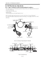
Adjustment > VCR Mechanism Adjustment
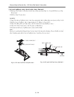
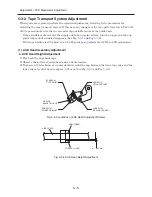
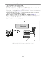
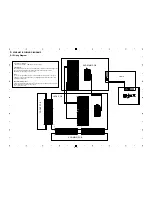
(2) FM Output Flatness Adjustment (Supply and Take-up Guide Roller Adjustment)
1) Play back the alignment tape.
2) Connect the oscilloscope CH-1 probe to TP3 (ENVELOPE) and CH-2 probe to TP4 (Head S/W-
Trigger), and then trigger the oscilloscope from CH-2.
(See Fig. 5-3-6)
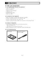
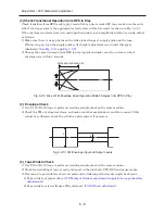
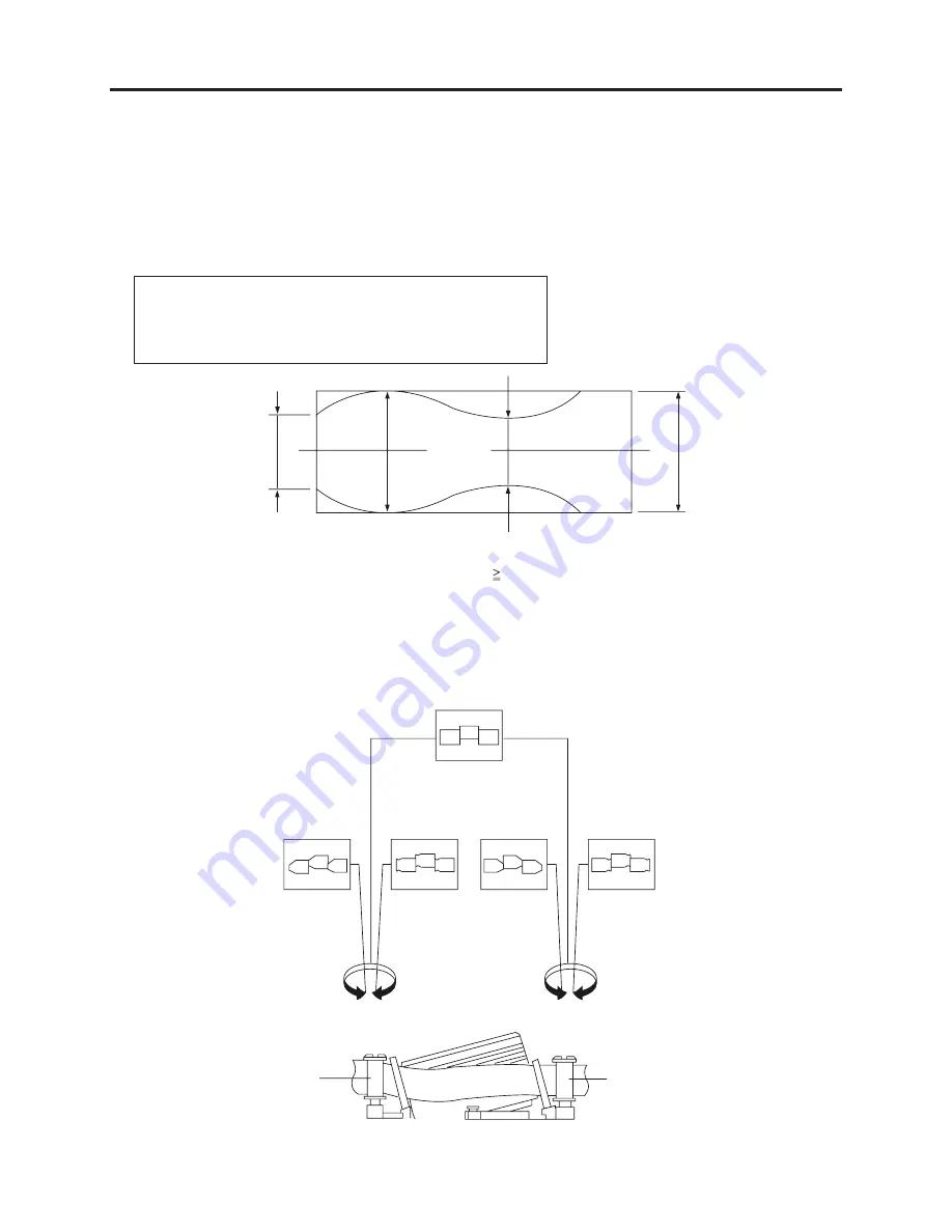
3) Observe the FM envelope waveform, and confirm that amplitudes b, c and d are all at least 63%
of the FM maximum amplitude (a in the figure).
If these specifications are not satisfied, perform the following adjustments:
a=Maximum output of FM envelope.
b=Minimum output of FM envelope at the entrance side.
c= Minimum output of FM envelope at the center point.
d=Maximum output of FM envelope at the exit side.
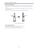
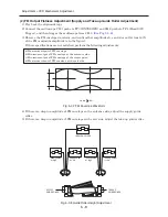
4) If there is a drop in amplitude of FM envelope on the entrance side, adjust the supply guide
roller.
5) If there is a drop in amplitude of FM envelope on the exit side, adjust the take-up guide roller.
Fig. 5-3-7 FM Envelope Waveform
Fig. 5-3-8 Guide Roller Height Adjustment
a
c,b,d/a
63%
b
c
d
IDEAL ENVELOPE
Supply height
too high
SUPPLY
GUIDE ROLLER
TAKE-UP
GUIDE ROLLER
Supply height
too low
Take-up height
too high
Take-up height
too low


