


5 - 9
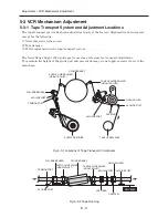
Adjustment > VCR Mechanism Adjustment
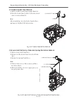
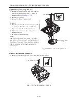
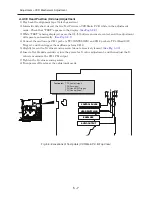
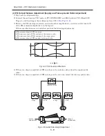
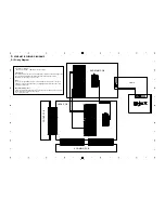
(3) Check Transitional Operation from RPS to Play
Check transition from RPS mode to play mode: Using a pre-recorded SP tape, make sure the entry
side of envelope comes to the appropriate steady state within 3 seconds (as shown in Fig. 5-3-9).
If the envelope waveform does not reach specified peak-to-peak amplitude within 3 seconds, adjust
as follows:
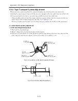
1) Make sure there is no gap between the roller lower flange of supply guide and the tape.
If there is a gap, turn the supply guide roller height adjustment screw until this gap is
eliminated.
(See Fig. 5-3-1
and
Fig. 5-3-2)
2) Change the operation mode from RPS to play (again) and make sure the entrance side of
envelope rises within 3 seconds.
Fig. 5-3-9 Rise of FM Envelope when Operation Mode Changes from RPS to Play
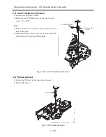
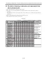
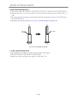
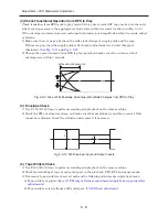
(4) Envelope Check
1) Use T-120 (E-120) tape to perform recording and playback on the same machine.
2) Check the FM envelope waveform, and make sure that amplitudes A and B are equal. If this
cannot be confirmed, check the cylinder, and replace it if necessary.
Fig. 5-3-10 FM Envelope Input and Output Levels
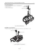
(5) Tape Wrinkle Check
1) Use T-160 (E-180) tape to perform recording and playback on the same machine.
2) Check for wrinkling of tape at each guide post in the playback, FPS, RPS and pause modes.
3) If excessive tape wrinkle is observed, perform the following adjustments in playback mode:
a) Tape wrinkle at guide rollers:
(2) FM output flatness adjustment (supply/take-up guide roller
adjustments)
b) Tape wrinkle at lower flange of #8 guide post:
(1) ACE head adjustment
A
B
ENTRANCE SIDE ENVELOPE


